


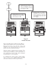
Beltpack Set-Up
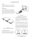
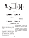
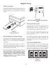
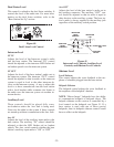
Headset Connection
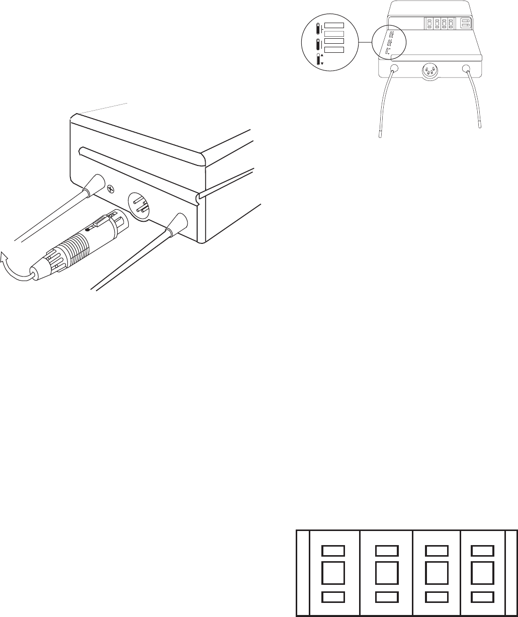
Insert the headset/microphone into the connector on
the bottom on the unit. See the headset connection
diagram (Figure 8) if a unit other than Telex headset
is used.
Figure 33
Connecting Headset
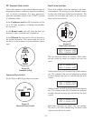
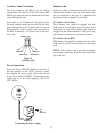
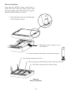
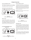
RF Transmit/Receive Channel Switches
Allows the user to select which of the two RF chan-
nels the unit is on. The transmit channel selected,
either “A” or “B”, is the frequency of the beltpack’s
transmitter.
The receiver channel selected, either “A” or “B”, is
the frequency the beltpack’s receiver is at. The fre-
quencies are listed on the label which is located un-
der the beltpack’s battery pack.
The base station’s transmit frequency must
match the beltpack’s receive frequency. Also the
base station’s receiver must match the beltpack’s
transmit frequency. Typically the base station
switches are both set to “A” or both to “B” and
the beltpacks are set to match.
Figure 34
RF Channel Switches and RF Transmit Mode
Switch
RF Transmit Mode Switch
Allows the operator to select two different types of
transmitting modes; Push-to-talk or
Push-to-transmit. For most operations, place the
transmitter switch in the “Push-to-talk" mode.
In the “Push-to-talk” mode the RF transmitter will
be on at all times regardless of whether the talk
switch is on or off.
In the “Push-to-transmit” mode, the transmitter will
be on only when the talk button is activated. The
transmitter will be turned off when the talk button is
deactivated.
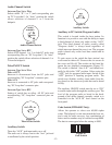
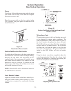
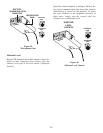
Code Switch (TR-600C Only)
Allows the operator to select over 65,000 cipher
codes. The beltpack’s code must match the base sta-
tion’s code for audio recovery. Any combination of
letters and/or numbers may be selected except 0000.
The data is unencrypted when the setting is 0000.
Figure 35
Code Switch
-18-
A
F2
3
A
B
TRANSMIT CHANNEL
A
B
RECEIVECHANNEL
PUSH TO
TALK
SERIAL No.
PUSH TO
TRANSMIT
A
F2
3