


1 − Introduction
TASCAM CD-RW901 9
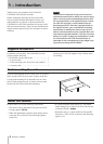
Never use a stabilizer or printable discs
Using commercially available CD stabilizers or print-
able recordable discs with this player will damage the
mechanism and cause it to malfunction.
NOTE
Never use a disc that has had a stabilizer mounted
to it. The residual adhesive may cause the disc to
stick to the turntable of the CD-RW901. If it sticks
to the turntable, you will need a technician to get it
out.
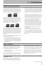
Connections
The following should be noted when you connect the
unit to other equipment.
It is possible to connect the unit’s
DIGITAL COAXIAL
IN
,
DIGITAL OPTICAL IN
,
DIGITAL IN (AES/EBU)
,
and balanced or unbalanced
ANALOG INs (L, R)
to
other equipment at the same time. However, the unit
can receive signals from only one digital input at a time.
Currently selected input jack is shown on the display.
Audio signals output from the unit are output from the
balanced or unbalanced
ANALOG OUT
jacks, as well as
from the
DIGITAL COAXIAL OUT
,
DIGITAL OPTICAL
OUT
and
DIGITAL OUT (AES/EBU)
connector simulta
-
neously (but not from the digital outputs in stop mode).
Currently selected input jack is shown on the display.
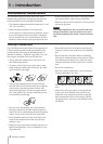
Beware of condensation
If the unit (or a compact disc) is moved from a cold to a
warm place, or used after a sudden temperature change,
there is a danger of condensation; vapor in the air could
condense on the internal mechanism, making correct
operation impossible. To prevent this, or if this occurs,
let the player sit for one or two hours at the new room
temperature before using.
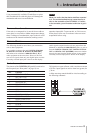
The pinouts of the CONTROL I/O (parallel) terminal on
the rear panel (see “Rear panel” on page 11) are:
Pin Function
1 STOP TALLY OUT
2 REC TALLY OUT
3 SKIP (forward) IN
4 SKIP (back) IN
5 EOM TALLY OUT
6 REC IN
7 CALL IN
8 GND
9 PLAY TALLY OUT
10 READY TALLY OUT
11 FADER, START/STOP
12 STOP IN
13 PLAY IN
14 READY IN
15 +5V
a
a. The maximum current supplied from this terminal is 50 mA.
Tall signals are open collector, with a maximum current
of 50 mA. Input signals are active when low (groun) for
≥ 30 ms.
A fader start/stop control should be wired according to
the following schematic:
Control connections