


Daily User
Requirements
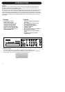
The P2 is correctly connected and loaded with
relevant Front Presets by the Administrator and
powered on.
Lock
The Administrator can decide to activate
different levels of Lock functions. These may
include lock of front panel key operation and/or
lock of the Wizard and Bypass functions.
By the choice of the Administrator the selected
Lock/Unlock function can be
activated/deactivated either by:
- pressing LOCK followed by a four digit code
specified by the Administrator or,
- holding lock for approx 2.5 seconds.
Selecting Presets
Press relevant preset key (1-8) to load preset.
Presets can be loaded only if these keys are
unlocked, (see above).
Presets are “total recall” presets. They set up
all levels, I/O settings and algorithm parameters.
Presets are defined by the experts user to
perfectly match the downstream signal
destination.
Wizard
The Wizard can be activated only if the Wizard
functions are unlocked. (see “Lock” section
above).
Once the Wizard is activated the P2 Level pilot
examines the program material and
automatically suggests optimal compression
settings for highest output. The Wizard can be
set by the Administrator to calculate three
levels of compression; Low, Medium and High.
Administrator
More details on page 18-21 - and setup page
10 for reference.
Requirements
One P2 Level Pilot, a Pentium computer with
Windows 95, 98, NT, 2000, ME or XP installed.
Installation of TC Icon Editor Software
Enter CD, open directory, run Setup and follow
instructions.
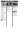
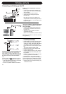
Connecting P2
• Connect a PC COM port to the P2 RS232 In.
If possible, notice which computer COM port
you have connected to.
• Programming the P2 does not necessarily
require audio to be connected. However, if
audio connections are
needed connect audio
according to Setup illustrations on page 10.
Getting started with the TC Icon Editor
• Power up the P2 and start the TC Icon
software on your computer.
• Go to the Setup/Devices/Port page to select
which COM(1-4) port you you have
connected to. (per default the Editor will look
at COM ports (1-4) automatically.
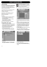
• Go to the Setup/Devices/Select page. Press
DETECT and assign the detected P2 to one
of the 8 device locations in the right side of
the display. Simply press any of the 8 keys.
• Press the ICON key in the upper left corner
to go the pages from where all local P2
parameters are controlled.
Library Page:
handles presets
System Page: handles Clock, Level trims,
Lock functions and the variable yellow LED
Threshold.
Engine:
All algorithm parameters.
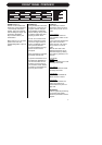
Cloning P2’s using a PCMCIA card
This is the function used by the Administrator to
clone multiple P2 using a PCMCIA card.
• Load appropriate presets into Front Panel
Bank of the P2 you wish to clone.
• Insert an unprotected PCMCIA card into the
P2 Card slot. (protection key is located on
the edge of the card).
• Go to the System/Card page.
• Decide whether you wish to exclude System
Preset that holds overall Clock settings,
Analog Trim levels, Dither, Status Bit settings
and settings for GPI. To exclude System
Preset activate the “Exclude System Preset”
key.
Then press CREATE CLONE CARD.
• Remove card and go to the target P2 unit.
• Insert the card and power up using the front
panel POWER key while holding the LOCK
key pressed.
• Press the LOCK key again. In this mode the
LOCK key operates as “CONFIRM”.
BYPASS can be used to abort operation.
• The target P2 is now loaded with the
information present on the card.
5
QUICK START