


4
TASCAM US-2x2/US-4x4
2 – Names and functions of parts
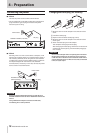
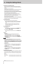
Front panel
w78 90q
12 3456
7
1
2
3 4 5
6
8
0
q
w
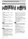
US-4x4 front panel US-2x2 front panel
1 SIG indicators
The SIG indicators light green when signals (of at least −32
dBFS) are input through the IN1/IN2 jacks (and US-4x4 IN3/
IN4 jacks).
2 PEAK indicators
The PEAK indicators light red when signals that are about
to distort (−1 dBFS or higher) are input through the IN1/IN2
jacks (and US-4x4 IN3/IN4 jacks).
3 GAIN knobs
Use to adjust the input levels of the IN1/IN2 jacks (and
US-4x4 IN3/IN4 jacks).
Adjust these so that the PEAK indicators do not light red.
4 USB indicator
This lights when the USB connection is working.
5 LINE OUT knob
Use to adjust the output level of the LINE OUT 1-2 jacks.
6 PHONES knob
Use to adjust the output level of the PHONES jack ( 1 and
2 jacks on US-4x4).
CAUTION
Before connecting headphones, minimize the volume with
the PHONES knob. Failure to do so might cause sudden loud
noises, which could harm your hearing or result in other
trouble.
7 Phantom power switch/indicator
Use this switch to provide +48V phantom power to the IN1/
IN2 jacks (and US-4x4 IN3/IN4 jacks).
The indicator lights when the phantom power switch is set
to +48V.
CAUTION
•
Set the LINE OUT and PHONES knobs to their minimum
values before changing the phantom power setting.
Depending on the connected mics, sudden loud noises from
monitoring equipment could occur, and this could damage
the equipment or harm hearing.
•
The phantom power switch changes the setting for both
US-2x2 input channels (all four US-4x4 input channels)
simultaneously.
•
Do not connect or disconnect mics when the phantom
power switch is set to +48V.
•
Set the phantom power switch to +48V only when using a
condenser microphone that requires phantom power.
Turning phantom power +48V when a dynamic mic or other
mic that does not require it is connected could damage this
unit and connected equipment.
•
Do not supply phantom power to an unbalanced dynamic
mic.
•
Supplying phantom power to some ribbon mics will break
them. If you are unsure, do not supply phantom power to a
ribbon mic.
•
If you connect this unit to a laptop computer that is running
on battery power and set the phantom power switch to
+48V, the computer battery charge will be consumed more
quickly.
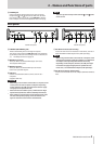
8 IN1/IN2 (BALANCED/UNBALANCED) jacks
These input jacks are XLR/TRS combo jacks on the US-2x2
and separate XLR and standard TRS jacks on the US-4x4.
Use the MIC/LINE INST switches on the front of the unit to
enable balanced line (MIC/LINE) input or unbalanced (INST)
input for the standard TRS jacks.
When directly connecting a guitar, bass or other instrument,
set the MIC/LINE INST switch to INST.
9 IN3/IN4 (BALANCED) jacks
These XLR analog mic input and standard line level TRS jacks
are balanced input jacks.
NOTE
On the US-4x4, the IN1-IN4 (8, 9) inputs each have two
jacks (XLR and TRS). Do not input signals through both
jacks of the same input at the same time. If signals are
input through both at the same time, neither signal will be
received properly.
0 MIC/LINE INST switches
Set according to the IN1/IN2 jack input sources.
Set to MIC/LINE when connecting electronic instruments,
audio devices, mics and similar equipment.
Set to INST when connecting an electric guitar, electric bass
or other equipment with high output impedance.
q MONITOR BALANCE knob
When recording input signals, use this to adjust the
monitoring balance between the signals from this unit's
input jacks and from the computer.
The volume of signals input through this unit's input jacks
increase the more the MONITOR BALANCE knob is set
to the left (INPUT) and signals output from the computer
increase the more this is set to the right (COMPUTER).
This knob does not affect the recording level of input
signals.