


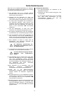


22
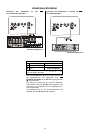
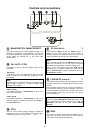
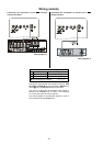
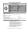
Connecting the sub-woofer to the
K6 DVD
surround receiver
Wiring diagram 5
Switch / adjustor settings
No.
Purpose
Control Voltage present
Automatic power-on
CTRL
Filter
FILTER OFF
The settings of the switches /
,
,
and
can be
changed as required.
The sub-woofer output signal (SUBW) from the K6 is
passed to the SC
LINK
socket
on the K6 via the
AKS6 adaptor and the SC
LINK
lead.
Since the SUBW signal is filtered in the K6, the Filter
switch
must be set to the 'FILTER OFF' position.
The control signal is present at the CONTROL socket of
the K6. It reaches the SC
LINK
socket
by the same
route, and triggers the automatic power-on circuit.
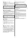
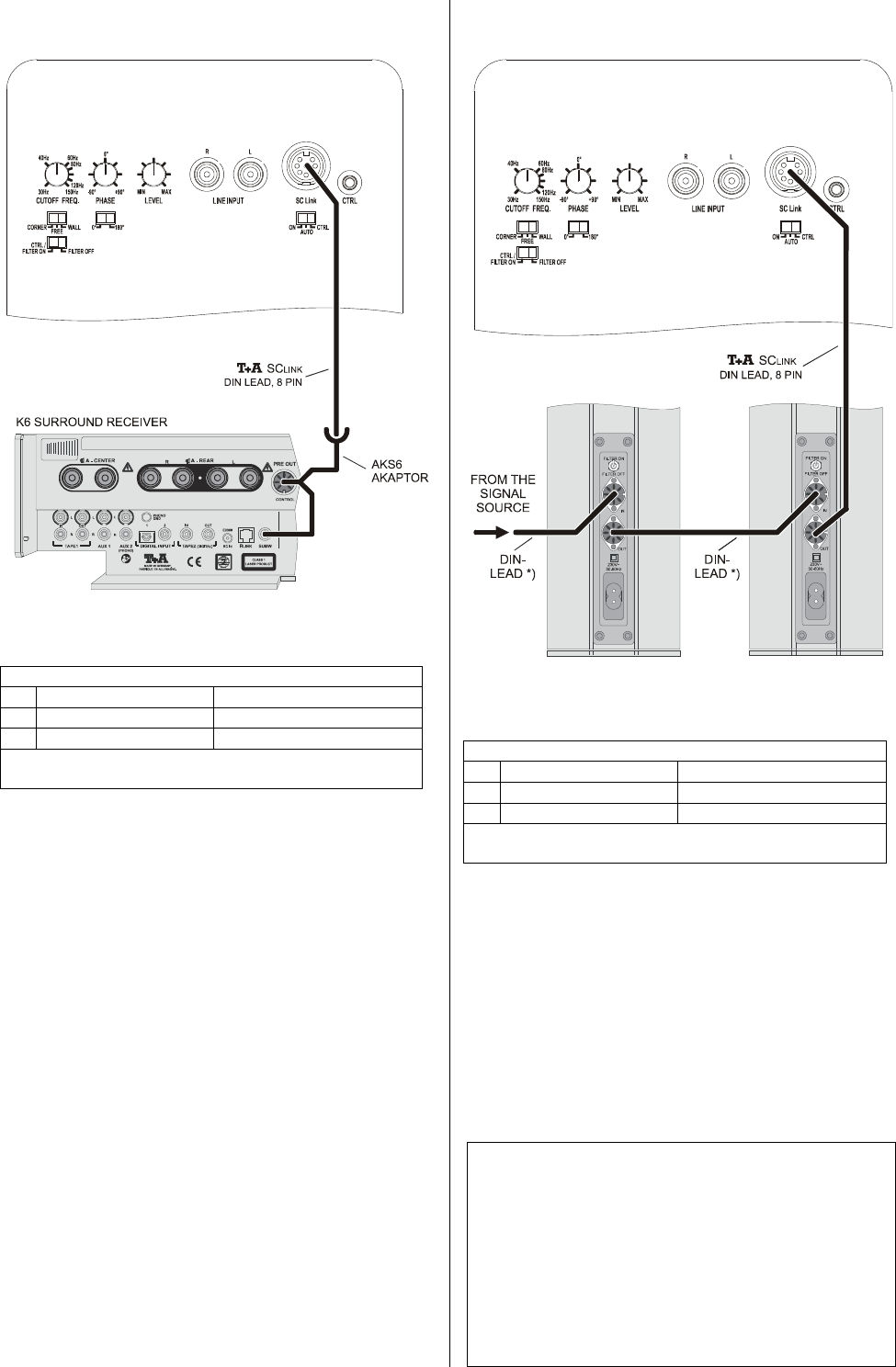
Connecting the sub-woofer to an active
TALIS
loudspeaker
*) 5-pin or 8-pin DIN lead
Wiring diagram 6
Switch / adjustor settings
No.
Purpose
Control Voltage present
Automatic power-on
CTRL
Filter
CTRL / FILTER ON
The settings of the switches /
,
,
and
can be
changed as required.
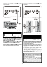
First connect the active speakers to the desired signal
source using a 5-pin or 8-pin DIN lead as described in
the TALIS operating instructions.
Connect the output socket of the 2nd active speaker to
the SC
LINK
input socket
of the sub-woofer using an
SC
LINK
lead.
The sub-woofer's internal crossover passes the low-
frequency part of the signal to the sub-woofer.
If the active speakers are switched on and off using a
control voltage, the control voltage is also passed to the
sub-woofer via the SC
LINK
lead. This triggers the sub-
woofer's automatic power-on circuit.
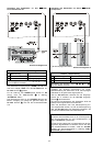
Notes:
If you use this method of connection, you must select the
option 'Full range' for the front loudspeakers when
setting up the surround decoder. This is carried out at
the loudspeaker configuration stage.
In this case the 'FILTER' switch on the TALIS loud-
speakers should be set to the 'CTRL / FILTER ON'
position. This avoids passing the low-frequency part of
the signal to the TALIS units, avoiding undue stress on
the speakers, and allowing them to operate cleanly at
higher levels.