


21
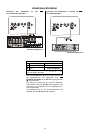
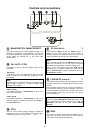
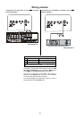
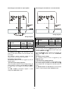
Connecting the sub-woofer to a pre-amplifier
Wiring diagram 3
Switch / adjustor settings
No.
Purpose
No
control
voltage
* Control
voltage
present
Automatic power-on
AUTO
CTRL
Filter
CTRL /
FILTER ON
CTRL /
FILTER ON
The settings of the switches /
,
,
and
can be
changed as required.
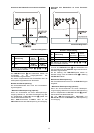
The LINE IN sockets
on the sub-woofer are con-
nected to the output sockets of the pre-amplifier using
Cinch leads.
The speaker's internal crossover passes the low-
frequency part of the signal to the sub-woofer.
Use without control voltage:
The automatic power-on circuit is triggered by the pre-
amplifier signal.
* Use with control voltage (optional):
If the pre-amplifier features a control voltage output, this
control voltage is passed to the SC
LINK
socket
via
an adaptor lead. This triggers the automatic power-on
cir-cuit.
The P 1220 R pre-amplifier supplies a control
voltage at the CRTL OUT socket.
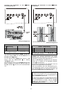
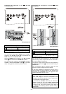
Connecting the sub-woofer to a surround decoder
Wiring diagram 4
Switch / adjustor settings
No.
Purpose
No
control
voltage
* Control
voltage
present
Automatic power-on
AUTO
CTRL
Filter
FILTER OFF
FILTER OFF
The settings of the switches /
,
,
and
can be
changed as required.
The Cinch lead carrying the SUB OUT signal from the
surround decoder is connected to one of the sub-
woofer's LINE IN sockets
.
Since the SUB OUT signal is filtered in the decoder, the
Filter switch
must be set to the 'FILTER OFF'
position.
Use without control voltage:
The automatic power-on circuit is triggered by the
SUB OUT signal.
* Use with control voltage (optional):
If the surround decoder features a control voltage output,
this control voltage is passed to the SC
LINK
socket
via an adaptor lead. This triggers the automatic power-on
circuit.
The DD 1210 R and DD 1510 R surround decoders
supply a control voltage at the 5.1 OUTPUT socket.