


4
IN3264 / IN3268 OPERATION MANUAL - REV. 1.3 01/04/01 ©1999 INLINE, INC.
Opening the J2, J3 and J4 pins will remove the 75 ohm termination for each color. This setting allows
users to connect a cable such as the IN9041 to the input and utilize a local monitor. Please note that if
there is no local monitor and the jumper pins are set to this position, there will be unnecessary “blooming”
or overdriving of the other four outputs.
The input jumper pins (J8, J10 and J12) must be closed at all times. If any of these jumpers are open
there will be no output because the pins are directly connected to the 15-pin input connectors (jumper pins
J8, J10 and J12 are used to interface the top and bottom boards of the IN3268 and should not be adjusted).
The factory default setting has them all closed. This allows the signal to be processed into the DA and
result in the proper 1 x 4 operation.
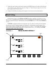
The IN3268 is very similar in operation and configuration to the IN3264. This unit has the same type of
board for the other four outputs, but the jumper pins on the top and the bottom boards of the IN3268 have
different configurations.
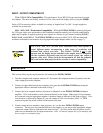
The bottom board should have all of the jumper pins closed except J2, J3 and J4, which remove the
termination and allow the top board to disengage the input. To place the proper 75 ohm termination to the
input, J2, J3 and J4 on the top board must be closed as well. The configuration of the top board is a little
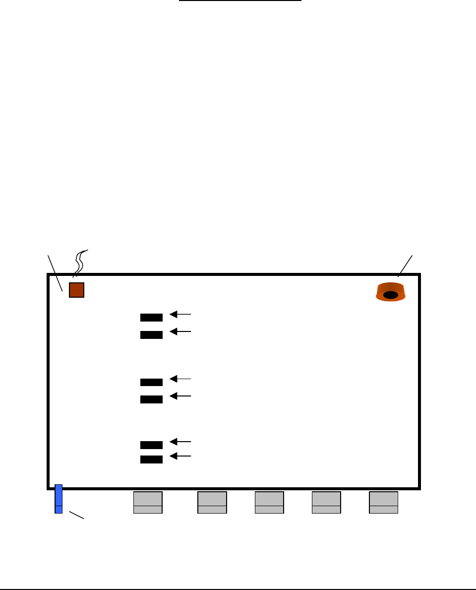
different because there are only two sets of jumpers per color (see Diagram 2-1).
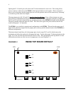
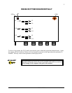
DIAGRAM 2-1 IN3268 TOP BOARD DEFAULT
LED COIL
H-POT
J2
J9
J3
J11
J4
J13