


3
©1999 - INLINE, INC. IN3264 / IN3268 OPERATION MANUAL - REV 1.3 01/04/01
5. Connect the round connector on the power supply to the POWER input jack (located on the back panel
of the distribution amp, immediately adjacent to Output 4.) Connect the power adapter box side of the
power supply to the A/C power source.
6. Complete the installation by turning on the computer, local monitor and remote data monitors.
Default Settings
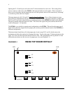
Among the many features of the IN3264 and IN3268 Distribution Amplifiers is the ability to not only
have 1 x 4 or 1 x 8 configurations (respectively), but, by unterminating the input impedance, users can add
a loop-out to other DAs as well. This effectively converts the IN3264 into a 1 x 5 DA, and the IN3268 into
a 1 x 9.
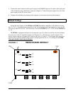
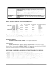
The IN3264 is equipped with three sets of jumper pins per color (three for red, three for blue and three
for green) for a total of 9 individual jumpers (see Diagram 1-1). Each one has a specific purpose. The
factory default setup has all jumper pins closed except for J9, J11 and J13. These jumper pins are there to
be used in the event that another board is added, converting the DA into a 1 x 8, resulting in the IN3268.
These pins should remain open at all times.
DIAGRAM 1-1 IN3264 BOARD DEFAULT
LED COIL
H-POT
J8 J2
J9
J10 J3
J11
J12 J4
J13