


DVI, VGA, and Component Video Pattern Generator
5
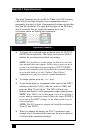
2. Installation
1. Plug the supplied AC adapter to the Power input connector located
on the rear of the unit. Use the supplied adapter or a 100%
equivalent only. There’s a small green LED that turns on when the
unit is powered up.
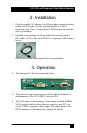
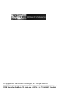
2. Included in the package are all the cables that you may need: a
DVI cable, a VGA cable, and a HD15 to component Cable (shown
below)
Choose and use the cable required for your application.
3. Operation
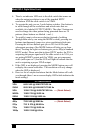
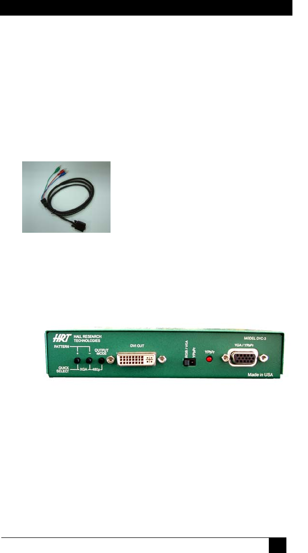
¾ The front panel of the unit is pictured below:
¾ There are two output connectors on the box that are both active
simultaneously. One VGA (HD15) and one DVI.
¾ The VGA output is dual purpose. It can output standard RGBHV
VESA signals similar to those that are output by most PC’s, as
well as YPbPr component video output. The output mode of the
HD15 connector is determined by a small slide switch.