


XLogic Mic Amp Owner’s Manual
Page 22
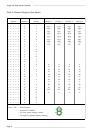
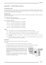
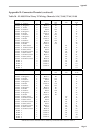
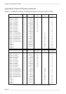
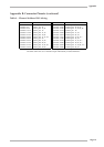
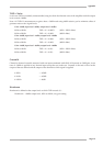
Appendix B: Connector Pinouts (continued)
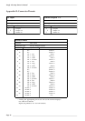
Table 3c - XL 9000 DL to 25way ‘D’ Wiring: Channels 17-24 / 41-48 / 65-72 / 89-96
Signal
Cable #
Colour
DL Audio
DL Control
25wD Male
Pin
Pin
17-20
Channel
17
Positive
5
Red
1
L1
2
Channel
17
Negative
5
Black
1
K1
15
Channel
17
Screen
5
Screen
1
J1
1
Channel
18
Positive
5
Red
2
L2
4
Channel
18
Negative
5
Black
2
K2
17
Channel
18
Screen
5
Screen
2
J2
14
Channel
19
Positive
5
Red
3
L3
7
Channel
19
Negative
5
Black
3
K3
20
Channel
19
Screen
5
Screen
3
H1
6
Channel
20
Positive
5
Red
4
L4
9
Channel
20
Negative
5
Black
4
K4
22
Channel
20
Screen
5
Screen
4
H2
19
Channel
17
Gain control
5
Red
5
L1
3
Channel
17
Switch Control
5
Black
5
K1
16
Channel
18
Gain control
5
Red
6
L2
5
Channel
18
Switch Control
5
Black
6
K2
18
Channel
19
Gain control
5
Red
7
L3
8
Channel
19
Switch Control
5
Black
7
K3
21
Channel
20
Gain control
5
Red
8
L4
10
Channel
20
Switch Control
5
Black
8
K4
23
ID Bit
1
5
Screen
5
J1
11*
ID Bit
2
5
Screen
6
J2
n/c
ID Bit
3
5
Screen
7
H1
12*
ID Bit
4
5
Screen
8
H2
n/c
ID Bit
5
n/c
Signal
Cable #
Colour
DL Audio
DL Control
25wD Male
Pin
Pin
21-24
Channel
21
Positive
6
Red
1
L5
2
Channel
21
Negative
6
Black
1
K5
15
Channel
21
Screen
6
Screen
1
H7
1
Channel
22
Positive
6
Red
2
L6
4
Channel
22
Negative
6
Black
2
K6
17
Channel
22
Screen
6
Screen
2
H8
14
Channel
23
Positive
6
Red
3
L7
7
Channel
23
Negative
6
Black
3
K7
20
Channel
23
Screen
6
Screen
3
J7
6
Channel
24
Positive
6
Red
4
L8
9
Channel
24
Negative
6
Black
4
K8
22
Channel
24
Screen
6
Screen
4
J8
19
Channel
21
Gain control
6
Red
5
L5
3
Channel
21
Switch Control
6
Black
5
K5
16
Channel
22
Gain control
6
Red
6
L6
5
Channel
22
Switch Control
6
Black
6
K6
18
Channel
23
Gain control
6
Red
7
L7
8
Channel
23
Switch Control
6
Black
7
K7
21
Channel
24
Gain control
6
Red
8
L8
10
Channel
24
Switch Control
6
Black
8
K8
23
ID Bit
1
6
Screen
5
H7
n/c
ID Bit
2
6
Screen
6
H8
24*
ID Bit
3
6
Screen
7
J7
12*
ID Bit
4
6
Screen
8
J8
n/c
ID Bit
5
n/c
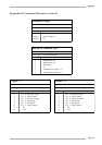
* Pinout shown is for channels 1-24. For other bays connect id. bits as shown in Table 4.