


XLogic Mic Amp Owner’s Manual
Page 18
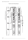
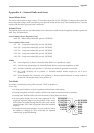
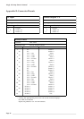
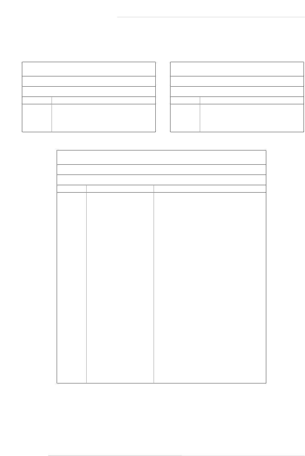
Appendix B: Connector Pinouts
Mic Input
Location:
Front Panel
Conn' Type:
XLR Female
Pin
Description
1
Chassis
2
Audio +ve
3
Audio -ve
Channel Outputs 1 - 4
Location:
Rear Panel
Conn' Type:
XLR Male
Pin
Description
1
Chassis
2
Audio +ve
3
Audio -ve
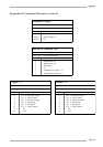
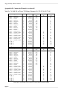
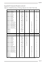
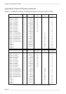
Audio/Control
Location:
Rear Panel
Connector Type:
25-way D-type Female
Pin
Description
Notes
1
0V
Screen
1
14
0V
Screen
2
2
Ch
1
Pos
Red
1
15
Ch
1
Neg
Black
1
3
Ch
1
Gain
Red
5
16
Ch
1
Switch
Black
5
4
Ch
2
Pos
Red
2
17
Ch
2
Neg
Black
2
5
Ch
2
Gain
Red
6
18
Ch
2
Switch
Black
6
6
0V
Screen
3
19
0V
Screen
4
7
Ch
3
Pos
Red
3
20
Ch
3
Neg
Black
3
8
Ch
3
Gain
Red
7
21
Ch
3
Switch
Black
7
9
Ch
4
Pos
Red
4
22
Ch
4
Neg
Black
4
10
Ch
4
Gain
Red
8
23
Ch
4
Switch
Black
8
11
ID Bit
1
Screen
5*
24
ID Bit
2
Screen
6*
12
ID Bit
3
Screen
7*
25
ID Bit
4
Screen
8*
13
ID Bit
5
N/C
*
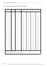
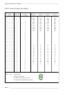
Linking the appropriate pins to 0V will set the channel displays.
See Table 4 for details.
Inputs are pulled to +5V via 15K resistors.