


Appendix A – Internal links and fuses
Fuses (Mains Inlet)
The mains inlet contains a single 1 amp 1.25" time delay fuse (SSL Part No. 35FJJ310). To change it disconnect the
mains inlet, then using a small screwdriver prise open the mains selector cover. This contains the fuse. Test and
replace with the same type and value if necessary.
Internal Fuses
The internal power rails are also individually fused. These fuses should only be changed by suitably experienced
staff. They are listed below:
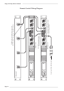
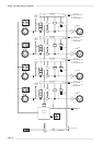
Fuses (629610X1 Power Regulator Card)
+48V FS1 - 500mA wire ended (SSL part No. 35F5E250)
Fuses (629601X1 Main Card)
+5V FS1 – 3 amp wire ended (SSL part No. 35F5E330)
+18V FS2 – 3 amp wire ended (SSL part No. 35F5E330)
+15V FS3 – 3 amp wire ended (SSL part No. 35F5E330)
–15V FS4 – 3 amp wire ended (SSL part No. 35F5E330)
–18V FS5 – 3 amp wire ended (SSL part No. 35F5E330)
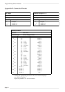
Links
LK1 Links output 0V to chassis. Normally fitted. Remove to capacitively couple.
LK3 Links chassis and analogue 0V. Normally fitted. Remove to increase impedance to 10Ω.
LK4 Test link. Normally set to position ‘a’. See below for details of operation in test mode.
LK5 Bit 5 link. Normally set to position ‘a’. Increases channel number display by 60 if set to
position.‘b’
LK6 Phase/Phantom link. Normally set to position ‘a’. Reverses default selection of remote control of
phase and +48 switches when set to position ‘b’.
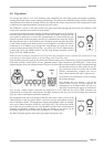
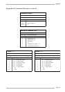
Test Mode
Test mode is selected by moving LK4 (screened ‘TEST’) to position ‘b’.
In test mode:
• All front panel switches are local, regardless of the remote switch setting.
• Pressing both phase and Hi-Z switches will drive the motor on that channel anti-clockwise.
• Pressing both –20dB and 48V will drive the motor on that channel clockwise.
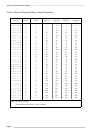
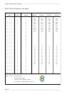
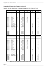
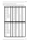
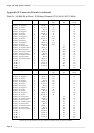
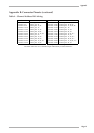
• All front panel displays have the same segments lit. The
displayed segments depend on the position of the rotary
BCD switch (accessible through the lid of the unit) and the
internal jumper, LK5. Table 2 (opposite) shows the available
displays.
• Normally the front panel displays are only written to when
the address is changed. In ‘Test’ mode they are updated
continuously to aid fault finding.
Appendix
Page 17
25-28/85-88
21-24/81-84
17-20/77-80
13-16/73-76
9-12/69-72
5-8/65-68
1-4/61-64
0
29-32/89-92
33-36/93-96
37-40
41-44
45-48
49-52
53-56
57-60