4.0 Operation
The XLogic Mic Amp is a 1U rack mounting unit containing four ultra high quality microphone amplifiers,
utilising Solid State Logic’s Super Analogue technology. The unit can be controlled locally, from the XLogic Mic
Amp Remote unit or from an XL 9000 console, allowing the mic amp to be placed close the microphone in order
to eliminate the signal degradation caused by long mic cables.
The ‘REMOTE’ switch on the right of the front panel (accessible through the hole above the ‘Remote’ LED)
switches the unit between remote and local modes.
In local mode all the front panel switches and the microphone gains can be set from
the front panel of the unit. Note that because of the servo motor and gear box the
gain control is stiffer than a normal SSL potentiometer. In remote mode the gain
controls and three of the front panel switches are controlled from either the XLogic
Mic Amp Remote unit or an XL 9000 console. The MON switch and either the phase
or 48V switch remain local. Which switch is local depends on whether the unit is
connected to an XL 9000 or to an XLogic Mic Amp Remote unit (and also on the
position of the internal PHAS/PHAN link – see section 3.6). The XL 9000 normally
controls 48V, Hi-Z and –20dB switches. The Mic Amp Remote normally controls
phase, Hi-Z and –20dB switches.
Please note that connecting a microphone to the XLogic Mic Amp with phantom power switched on is not advised as it may
cause damage to either the microphone or the input stage of the XLogic Mic Amp.
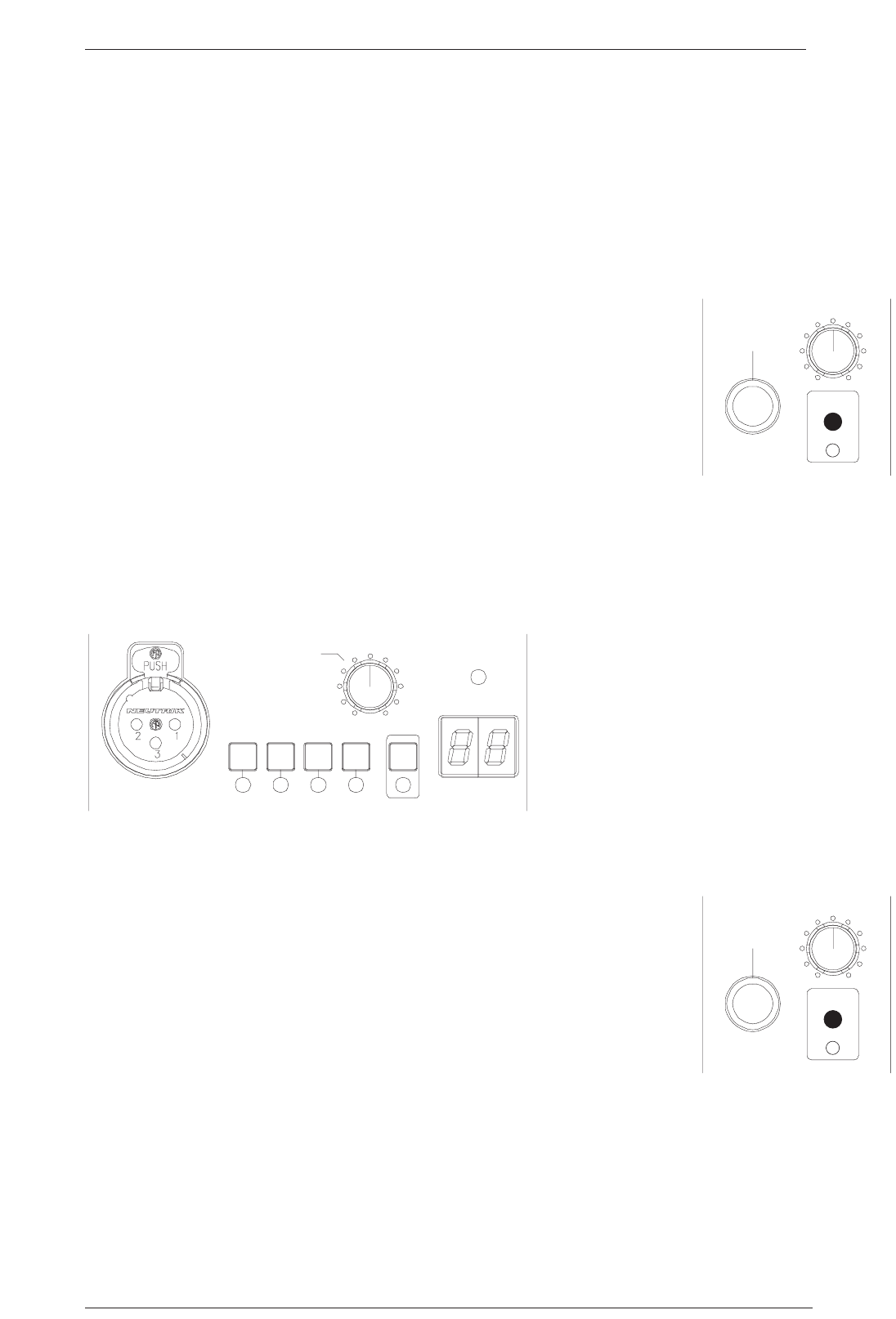
Each channel has an XLR input on the front panel. The mic amp gain is controlled by a motorised potentiometer.
Dedicated switches control phase reverse, phantom power, input impedance and 20dB pad. A dual seven
segment display shows the channel number. These are set from either an internal BCD switch (accessible through
the lid of the unit) or by links on the 25 way ‘D’
type connector on the rear of the unit. XL 9000
consoles automatically configure the unit to
show which channels the unit is connected to.
See section 3.6 for instructions on how to change
the channel displays.
Each channel has two outputs – one on the
Audio/Control 25 way ‘D’ type connector for
connection to an XL 9000 console and one on a
male XLR. Control inputs appear on both the 25
way ‘D’ type ‘Audio/Control’ connector for connection to an XL 9000 and also on two RJ45 connectors for
connection to an XLogic Mic Amp Remote. The RJ45 connectors also carry power to the remote unit. Note that
only one of the control inputs should be connected.
The headphone jack and level control at the left of the unit is fed by a mix of the
talkback input on the rear panel ‘MON’ connectors and any microphone channel
that is selected to ‘MON’. The headphone outputs and talkback inputs on multiple
units can be linked using the ‘MON IN’ and ‘MON OUT’ RJ11 connectors on the
rear of the unit (see sections 3.3 and 3.4). The MON switches inter cancel between
channels and between multiple units if they are linked, so any input can be
monitored without having to move the headphones to a different unit.
The block diagram opposite shows the signal path through the unit.
Operation
Page 15
SIGNAL
CHANNEL
GAIN
HI
Z
-20
dB
48V MON
ø
+18 +72
dB
MONITOR
REMOTE
MONITOR
REMOTE


