OPERATION AND CONTROLS
9
information on using filters with the amplifier
in AC coupled mode.
Gain Mode
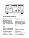
The allocation of gain throughout the
instrument is set using the GAIN MODE
pushbutton The Gain Mode is displayed by
two indicator LED’s: HIGH DYNAMIC
RESERVE and LOW NOISE. For a given
gain setting, a HIGH DYNAMIC RESERVE
allocates the SR560's gain toward the
output stages after the filters. This prevents
signals, which are attenuated by the filters
from overloading the amplifier. The LOW
NOISE setting allocates gain toward the
front-end in order to quickly "lift" low-level
(nV range) signals above the instrument's
noise floor.
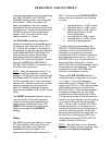
Gain
The instrument's gain is increased or
decreased using the GAIN pushbuttons.
Gain settings from 1 to 50,000 are available
and are displayed as the product of a factor
1, 2 or 5 and a multiplier (none (i.e. 1), 10,
100, 1,000 or 10,000). In addition to these
fifteen fixed gain settings, the user may
specify arbitrary gains through the UNCAL
feature. To set an uncalibrated or arbitrary
gain the user must press both Gain buttons
simultaneously, lighting the UNCAL LED. In
this mode by pressing the Gain Up or Gain
Down pushbuttons, the user may reduce the
calibrated gain in roughly 1% increments
from 100% down to 0% of the selected gain.
In contrast to other front-panel functions,
when in UNCAL the instrument's key-repeat
rate will start slowly and increase to a limit
as long as either Gain button is depressed.
Simultaneously pressing both Gain buttons
once again will restore the unit to the
previously calibrated gain setting, and turn
off the UNCAL LED.
Output
The outputs of the instrument are located
within the OUTPUT section of the front
panel. Two insulated BNCs are provided: a
600Ω output and a 50Ω output. The
amplifier normally drives high impedance
loads and the instrument's gain is calibrated
for high impedance loads. When driving a
600Ω load via the 600Ω output (or a
50Ω load via the 50Ω output) the gain of the
amplifier is reduced by two. The shields of
all the front-panel BNC’s are connected
together and form the amplifier's floating
ground.
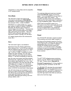
Reset
The OVLD LED indicates a signal overload.
This condition can occur when a signal is
too large or the dynamic reserve is too low.
Reducing the gain, reducing the input signal
and/or switching to the HIGH DYNAMIC
RESERVE setting should remedy this
condition. If an overload occurs with filter
settings of long time constants, the RESET
pushbutton will speed the SR560's recovery
from overload.
Status
The ACT LED indicates communications
activity over the SR560's optoisolated RS-
232 port. Please refer to Appendix A:
Remote Programming for further details on
programming the instrument via RS-232.
The BLANK LED indicates the optoisolated
BLANKING input (on the rear panel of the
SR560) is active. The SR560 responds to a
blanking input by internally grounding the
amplifier signal path after the front end and
before the first filter stage.


