


Starlet Owner’s Manual Page 7
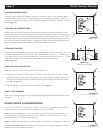
WIRING THE STARLETS 6 and 9
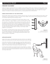
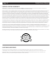
The Starlets 6 and 9 are bi-amplified, which means that one terminal is wired to
a single amplifier channel and the other terminal is wired to a separate amplifier
channel. Thus both terminals are always used in the Starlets 6 and 9. The end plate
bearing the SpeakerCraft logo and product name is the woofer terminal, and is
marked “woofers”. The blank plate is the tweeter terminal, and is marked “tweeters”.
(See Diagram 15)
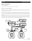
There are two options for bi-amping:
1. Use a single stereo amplifier for each speaker, with one channel for the woofer
and the other for the tweeter. This option is preferred if you have two identical
stereo amplifiers.
2. Use one amplifier for the woofers and a separate amplifier for the tweeters. This
option is preferred if you have two different stereo amplifiers. In this case, the
less powerful amplifier should be used on the tweeter section.
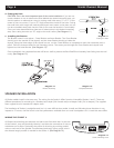
INSTALLATION IN A 2x4 STUD WALL
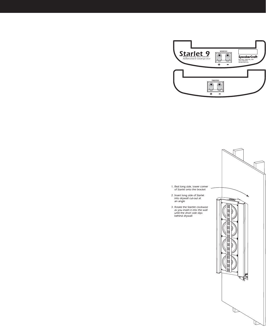
All Starlets are asymmetrical. Hold the Back Box/Driver Assembly by grasping
the tweeters, being careful not to touch the voice coils behind the tweeters.
The tweeter assembly is very strong, as the tweeter bridge is a cast aluminum
part. On the larger Starlets, it is advisable to have an assistant. Insert the long
side of the back box first, pushing it until the tweeter bridge stops further move-
ment. Then slip the short side into the cavity, moving the Starlet until the tweeter
bridge is centered. The proximity of the back wall will support the speaker while
the rest of the installation is completed. (See Diagram 16)
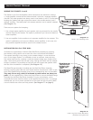
The Bezel/Flange Assembly is installed into the Back Box/Driver Assembly,
forming a strong clamp with the wall. Please observe that there are “tabs” on the
back of the Bezel/Flange Assembly that fit into corresponding slots on the baffles.
They only fit one way, which is indicated by small arrows on these two
parts. Use the supplied M4 x 45mm hex head screws to secure the Bezel/Flange
Assembly into the Back Box/Driver Assembly. For your convenience, we’ve
enclosed the correct sized hex driver in the supplied Accessory Pack. It is strongly
advised that you use a power screwdriver to save time and get a tight fit. Make
sure all of these hex screws are firmly seated. (See Diagram 17 on page 8)
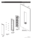
Diagram 15:
Starlet 6 and 9 Binding Posts
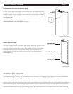
Diagram 16:
Insert Long Side of Back Box/Driver
Assembly into Drywall First