


INSTALLATION PREPARATION
NEW CONSTRUCTION
Starlets are designed to be installed into a standing wall, therefore no new construction
bracket is supplied.
There are some considerations for new construction to create the best possible sound:
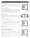
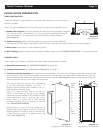
1. Double Thick Drywall: The clamp between the back box and front baffle is designed
for
1
⁄2" drywall (or any wall material in
1
⁄2"). If you are planning double thick drywall,
leave an area about 12" wide around the Starlet opening in single thickness.
(See Diagram 8)
2. Starlets are Heavy: Walls should be constructed with screws and the wallboard
should be glued to the studs. A few dollars worth of Elmer’s wood glue can work wonders in an in-wall installation.
3. Metal Studs: Avoid these in a wall supporting Starlets
4. Wire Routing: Install the speaker wires before the wallboard goes up (see “SPEAKER INSTALLATION” for wiring information)
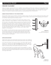
FINISHED WALL
When installing the Starlets in a finished wall, please follow these instructions carefully:
a. Determining Placement: See “SPEAKER PLACEMENT” on pages 3-4.
b. Locating Obstructions: See “Checking for Obstructions” on page 4.
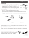
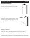
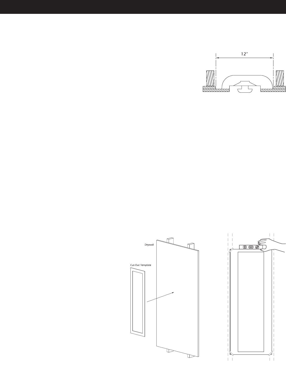
c. Tracing the Cut-Out Template: Your installation cut-out template is included in the packaging. Please be aware that there
are two sections: one is the cut-out template and the other is the paint mask. Be careful not to confuse the two. Place the
cut-out template at the location you have decided to install the Starlets. (See Diagram 9) Keep in mind that the flange will
extend beyond the cut-out on the sides, top and bottom.
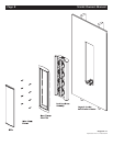
The cut-out takes into account the asymmetrical shape
of the Back Box/Driver Assembly. This gives a small
degree of lateral freedom when installing the 11
1
⁄2" wide
Back Box/Driver Assembly into a
typical 14
1
⁄2" wide stud bay. There is no real “up” or
“down” to the Starlet, so use the cut-out template to
determine the best position for the speaker in order to
avoid obstructions and to get the best acous- tic
results. There is a correct way to install the baf- fle
assembly, however, which is covered in the next sec-
tion, “SPEAKER INSTALLATION”.
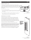
With the above in mind, use a level along the top or
bottom edge of the template so that the cut-out will be
aligned correctly. Use tape or tacks to hold the tem- plate
in place. Trace an outline of this pattern on the wall with a
pencil. (See Diagram 10)
Starlet Owner’s Manual Page 5
Diagram 8:
Double Drywall
Diagram 10:
Aligning the Cut-Out Template
Diagram 9:
Placing the Cut-Out Template