


NOTE:
• -XX, -X mean standardized parts, so they may
have some differences from the original one.
• Items marked “*” are not stocked since they
are seldom required for routine service. Some
delay should be anticipated when ordering these
items.
• The mechanical parts with no reference number
in the exploded views are not supplied.
• Hardware (# mark) list and accessories and
packing materials are given in the last of this
parts list.
•
Color Indication of Appearance Parts Example:
KNOB, BALANCE (WHITE) . . . (RED)
↑ ↑
Parts of Color Cabinet’s Color
• Abbreviation
CND : Canadian model
MY : Malaysia model
SP : Singapore model
AR : Argentina model
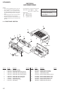
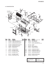
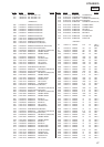
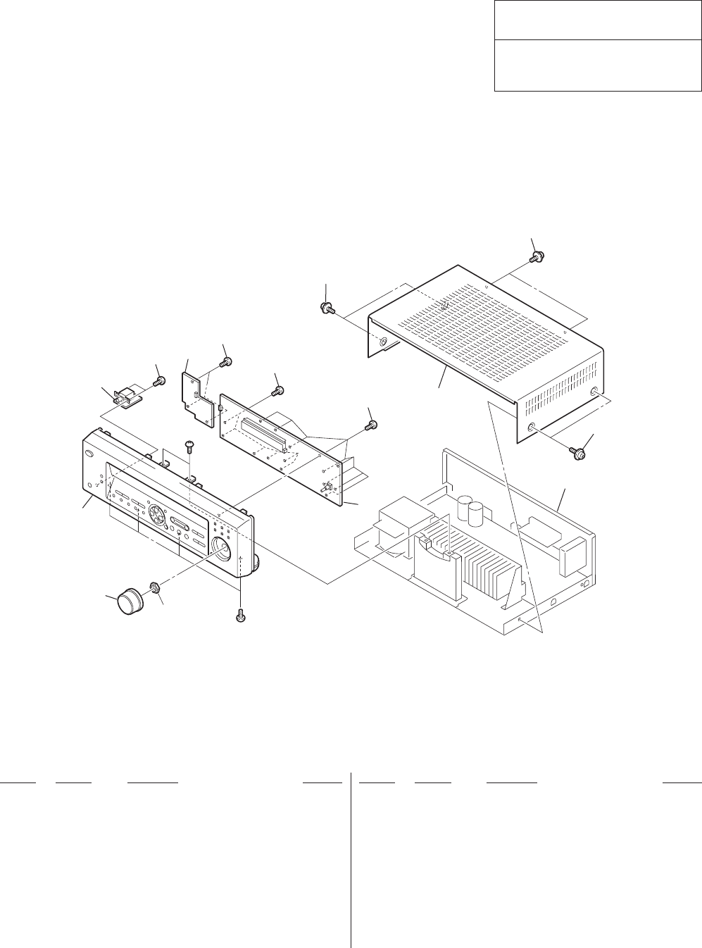
SECTION 4
EXPLODED VIEWS
20
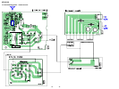
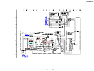
The components identified by mark 0 or
dotted line with mark 0 are critical for safety.
Replace only with part number specified.
Les composants identifiés par une marque
0 sont critiques pour la sécurité.
Ne les remplacer que par une pièce portant
le numéro spécifié.
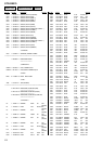
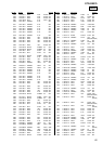
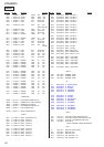
STR-DE375
Ref. No. Part No. Description Remarks Ref. No. Part No. Description Remarks
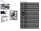
not
supplied
chassis sectio
n
6
6
6
5
7
3
4
4
8
4
4
#2
1
2
#1
1 4-232-113-01 KNOB (VOL) (BLACK)
1 4-232-113-11 KNOB (VOL) (SILVER)
2 X-4953-358-1 FRONT PANEL ASSY (BLACK)(AEP,UK)
2 X-4953-433-1 FRONT PANEL ASSY (SILVER)(AEP,UK)
2 X-4953-434-1 FRONT PANEL ASSY (BLACK)(E,SP,MY)
2 X-4953-688-1 FRONT PANEL ASSY (BLACK)(CND)
2 X-4953-763-1 FRONT PANEL ASSY (SILVER)(AR)
3 1-680-496-11 HEADPHONE BOARD
4 4-951-620-01 SCREW (2.6X8), +BVTP
5 4-232-118-01 CASE (BLACK)
5 4-232-118-21 CASE (SILVER)
6 4-210-291-01 SCREW (CASE 3 TP2) (BLACK)
6 4-210-291-11 SCREW (CASE 3 TP2) (SILVER)
7 1-680-497-11 POWER SWITCH BOARD
8 A-4475-762-A DISPLAY BOARD,COMPLETE (AEP, UK)
8 A-4475-856-A DISPLAY BOARD,COMPLETE (SP,MY)
8 A-4475-858-A DISPLAY BOARD,COMPLETE (E,AR)
8 A-4476-443-A DISPLAY BOARD,COMPLETE (CND)
#1 7-685-646-79 SCREW +BVTP 3X8 TYPE2 IT-3
#2 7-685-645-79 SCREW +BVTP 3X6 TYPE2 N-S
4-1. FRONT PANEL SECTION