


– 33 –
SECTION 7
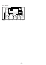
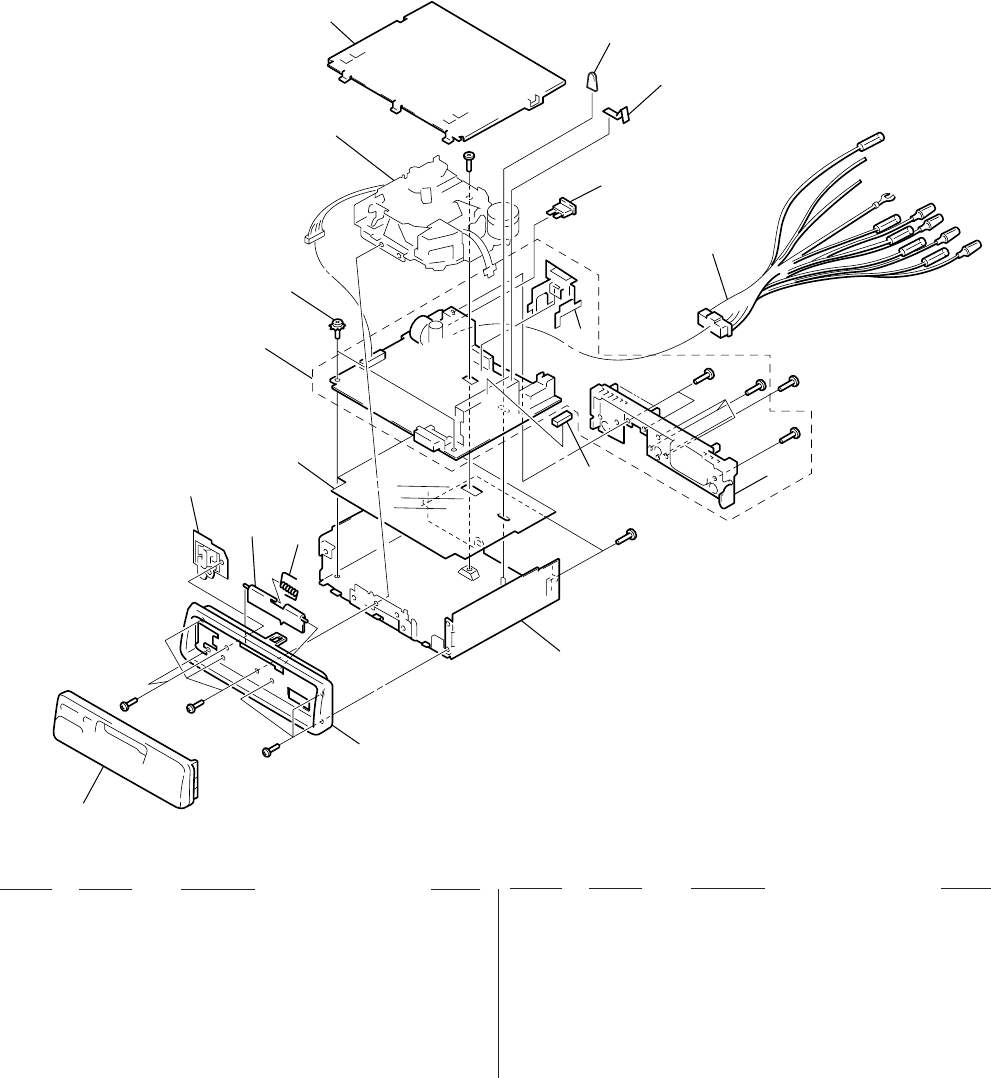
EXPLODED VIEWS
• Items marked “*” are not stocked since they
are seldom required for routine service. Some
delay should be anticipated when ordering
these items.
• The mechanical parts with no reference num-
ber in the exploded views are not supplied.
• Hardware (# mark) list and accessories and
packing materials are given in the last of the
electrical parts list.
NOTE:
• -XX and -X mean standardized parts, so they
may have some difference from the original
one.
• Color Indication of Appearance Parts
Example:
KNOB, BALANCE (WHITE) . . . (RED)
↑↑
Parts Color Cabinet's Color
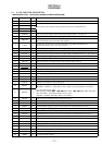
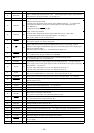
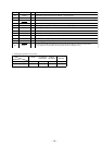
Ref. No. Part No. Description Remark
Ref. No. Part No. Description Remark
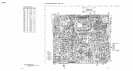
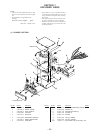
(1) CHASSIS SECTION
1 3-009-294-01 PANEL, SUB
2 3-935-003-01 SPRING, TORSION
3 3-932-205-21 DOOR, CASSETTE
4 X-3367-636-1 LOCK ASSY
* 5 3-010-377-01 INSULATOR
* 6 A-3313-396-A MAIN BOARD, COMPLETE
7 3-915-923-01 SCREW, GROUND POINT
* 8 X-3373-270-1 COVER ASSY
9 1-776-207-41 CORD (WITH CONNECTOR) (POWER)
* 10 3-009-809-01 BRACKET (IC)
* 11 3-010-517-01 HEAT SINK (BUS NON) (E)
12 3-935-014-01 CUSHION (U)
* 13 3-009-813-01 CHASSIS
14 3-012-859-01 CAP (25), RUBBER
15 3-937-650-01 PLATE (C), GROUND
F781 1-532-877-11 FUSE (BLADE TYPE) (AUTO FUSE) (10A)
MG-25F-136
F781
Front panel ass’y
#1
#2
#2
#2
#2
#2#2
#4
1
15
14
13
12
11
10
9
8
7
6
5
4
3
2
#3