


– 18 –
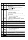
Pin No. Pin Name I/O Function
41 KEYACK I
Input of acknowledge signal for the key entry Acknowledge signal is input to accept function
and eject keys in the power off status On at input of “L”
42 BU IN I Battery detect signal input terminal “H”: battery on
43 MTLSEL I/O
44 DOLON I/O
45 AMSIN I
Whether a music is present or not from CXA2509AQ (IC301) is detected at auto music sensor
“L”: music is present, “H”: music is not present
46 ST I/O
47 AMS ON O
Tape auto music sensor control signal output to the CXA2509AQ (IC301)
“L” is output to lower the gain for audio level at FF/REW
48 N/R OUT O
Forward/reverse direction control signal output to the CXA2509AQ (IC301)
“L: forward direction, “H”: reverse direction
49 TAPMUT O Tape muting on/off control signal output to the CXA2509AQ (IC301) “H”: tape muting on
50 ILLON O
51 SD IN I
Station detector detect input from the FM/AM tuner unit (TU1)
Stop level for SEEK, BTM, etc. is determined SD is present at input of “H”
52 NOSESW I Detects the removal of the attaching and removing type front panel block “L”: attaching
53 TELMUTE I
Telephone muting signal input terminal At input of “L”, the signal is attenuated by –20 dB
Not used (fixed at “H”)
54 REL I Reel table rotation detect signal input from the take-up and supply reel sensor
55 ACCIN I Accessory detect signal input terminal “L”: accessory on
56 TESTIN I Setting terminal for the test mode “L”: test mode (normally fixed at “H”)
57 RC IN1 I Rotary remote commander shift key A/D input terminal
58 PW SEL I
Power select switch (S501) input terminal
“L”: position A (halt mode), “H”: position B (operation mode)
59 MTLIN I
Input terminal to set whether the auto metal function is present or not
“L”: auto metal function is present (fixed at “H”)
60 ADON O Power supply on/off control signal output for the A/D conversion
61 KEYSEL I Setting terminal for the key (fixed at “H”)
62 SEKOUTSEL I Active selection terminal for the SEKOUT (pin #•) (fixed at “L”)
63 COLORSEL I Setting terminal for the illumination color “L”: amber, “H”: green Not used (fixed at “L”)
64 LCDCE O Chip enable output to the liquid crystal display driver (IC901)
65 LCDCKO O Serial data transfer clock signal output to the liquid crystal display driver (IC901)
66 LCDSO O Serial data output to the liquid crystal display driver (IC901)
67 LCDINH O
Blank indicate control signal output to the liquid crystal display driver (IC901)
“L”: no display
68 UNICKI I Serial data reading clock signal input terminal for the unilink Not used (connected to pin &¡)
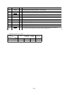
Input of FM stereo detection signal from FM/AM tuner unit (TU1), and output of forced
monaural control signal to FM/AM tuner unit (TU1) (Commonly used for stereo display input
and forced monaural output)
FM stereo detection at input of “L”, forced monaural at output of “L”
Dolby control in/out terminal
At initial mode: valid/invalid selection input of dolby function (“L” input: valid)
At normal mode: dolby on/off control signal output “H”: dolby on
Not used this function in this set (fixed at “H”)
METAL control in/out terminal
At initial mode: auto/manual mode selection input of METAL function “L”: manual mode
At manual mode: METAL on/off control signal output to the CXA2509AQ (IC301)
“H”: METAL on
At auto mode: input at MTLIN (pin %ª)
Power supply on/off control signal output terminal at the illumination and liquid crystal display
driver (IC901) “H”: power on
At power select switch (S501) on mode: “H” output at the accessory on
At power select switch (S501) off mode: “H” output at the power on