


– 15 –
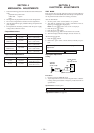
TUNER SECTION
0 dB=1 µV
Cautions during repair
When the tuner unit is defective, replace it by a new one be-
cause its internal block is difficult to repair.
Note: Adjust the tuner section in the sequence shown below.
1. FM Auto Scan/Stop Level Adjustment.
2. FM Stereo Separation Adjustment.
3. AM (MW) Auto Scan/Stop Level Adjustment.
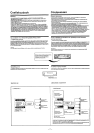
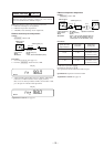
FM Auto Scan/Stop Level Adjustment
Setting:
[SOURCE] button: FM
Procedure:
1. Set to the test mode. (See page 14.)
2. Push the
[SOURCE] button and set to FM.
Display
3. Adjust with the volume RV2 on TU1 so that the “FM” indica-
tion turns to “FMI” indication on the display window.
But, in case of already indicated “FMI”, turn the RV2 so that
put out light “I” indication and adjustment.
Display
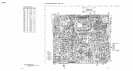
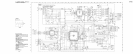
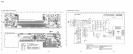
Adjustment Location: See page 16.
FM RF signal
generator
Carrier frequency : 98.0 MHz
Output level : 22 dB (12.6
µ
V)
Mode : mono
Modulation : 1 kHz, 22.5 kHz deviation (30%)
0.01
µ
F
set
antenna jack (J1)
FM
98.0
SHUF1
FM
98.0
SHUF1
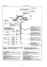
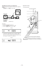
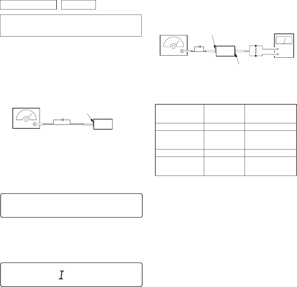
FM Stereo Separation Adjustment
Setting:
[SOURCE] button: FM
Procedure:
L-CH Stereo separation: A-B
R-CH Stereo separation: C-D
The separations of both channels should be equal.
Specification: Separation more than 28 dB
Adjustment Location: See page 16.
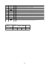
FM Stereo
Level meter Level meter
signal generator
connection reading (dB)
output channel
L-CH L-CH A
B
R-CH L-CH Adjust RV4 on TU1
for minimum reading.
R-CH R-CH C
D
L-CH R-CH Adjust RV4 on TU1
for minimum reading.
FM RF signal
generator
Carrier frequency : 98.0 MHz
Output level : 70 dB (3.2 mV)
Mode : stereo
Modulation : main: 1 kHz, 20 kHz deviation (26.7%)
sub: 1 kHz, 20 kHz deviation (26.7%)
19 kHz pilot: 7.5 kHz deviation (10%)
0.01
µ
F
set
antenna jack (J1)
+
–
speaker out terminal
level meter
4
Ω