


– 17 –
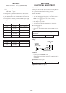
6-1. IC PIN FUNCTION DESCRIPTION
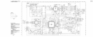
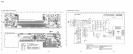
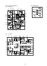
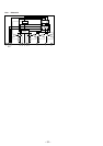
SECTION 6
DIAGRAMS
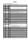
• MAIN BOARD IC501 µPD17707GC-529-3B9 (SYSTEM CONTROLLER)
Pin No. Pin Name I/O Function
1 AMSSEL I Setting terminal for the AMS selection fixed at “L”
2 POS3 I
3 POS2 I
4 POS0 I
5 POS1 I
6 TAPEON O Tape system power supply on/off control signal output terminal “H”: tape on
7 CM ON O Capstan/reel motor (M901) drive signal output terminal “H”: motor on
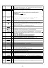
8 LM LOD O
Loading/tape operation motor control signal output to the MM1322XFBE (IC351)
(For the loading direction and forward side operation) *1
9 LM EJ O
Loading/tape operation motor control signal output to the MM1322XFBE (IC351)
(For the eject direction and reverse side operation) *1
10 TUNON O Tuner system power supply on/off control signal output to the BA3918 (IC611) “H”: tuner on
11 FM ON O FM system power supply on/off control signal output to the BA3918 (IC611) “H”: FM on
12 PW ON O Main system power supply on/off control signal output to the BA3918 (IC611) “H”: power on
13 MUT O Line muting control signal output terminal “H”: line muting on
14 VOLCE O Chip enable signal output to the electrical volume (IC331)
15 VOLCKO O Serial data transfer clock signal output to the electrical volume (IC331)
16 VOLSO O Serial data output to the electrical volume (IC331)
17 AMPON O Standby control signal output to the power amplifier (IC751) “L”: standby
18 AMPMUT O Muting control signal output to the power amplifier (IC751) “L”: muting on
19 DX/LO O Local/DX selection signal output to the FM/AM tuner unit (TU1) “L”: DX, “H”: local
20 NCO O Not used (open)
21 GND — Ground terminal
22 DSTSEL I Destination setting terminal (fixed at center voltage)
23 D-BASS I D-BASS switch (SW951) input (A/D input)
24 KEYIN1 I
Key input terminal (A/D input)
6, INTRO 1, REPEAT 2, 3, BL SKIP 6, ATA 5, MTL 4 keys input (LSW921 to LSW927)
25 KEYIN0 I
26 RC IN0 I Rotary remote commander shift key A/D input terminal
27 VSM I FM and AM (MW/LW) signal meter voltage detection input from the FM/AM tuner unit (TU1)
28 AMIFIN I AM (MW/LW) intermediate frequency detection signal input from the FM/AM tuner unit (TU1)
29 FMIFIN I FM intermediate frequency detection signal input from the FM/AM tuner unit (TU1)
30 VDD2 — Power supply terminal (+5V)
31 FM OSC I FM local oscillator detection signal input from the FM/AM tuner unit (TU1)
32 AM OSC I AM (MW/LW) local oscillator detection signal input from the FM/AM tuner unit (TU1)
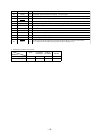
33 GND — Ground terminal
34 NCO O Not used (open)
35 EO1 O Main charge-pump control signal output terminal
36 TEST0 I Setting terminal for the test (fixed at “L”)
37 NCO O Not used (open)
38 SEKOUT O Seek control signal output to the FM/AM tuner unit (TU1)
39 MW SW O MW/LW selection signal output to the FM/AM tuner unit (TU1) “L”: MW, “H”: LW
40 BEEP O Beep sound output terminal
Tape position detect input from tape operation switch on the mechanism block
Key input terminal (A/D input)
OFF, SOURCE, MODE *, + ) + SEEK AMS, – = 0 SEEK AMS, VOLUME –,
SEL, VOLUME +, ATT, DSPL, BTM, LCL keys input
(LSW901 to LSW909, LSW930, LSW911 and LSW912)