


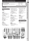

Hooking Up the Components
9
GB
COMPONENT VIDEO
SPEAKERS
IMPEDANCE USE 8 – 16Ω
Y
P
B
B-Y
P
R
R-Y
DVD/LD
IN
VIDEO 2
IN
MONITOR
OUT
R
L
R
L
SPEAKERS
IMPEDANCE USE 8 – 16
Ω
FRONT ACENTERSURROUND
AUDIO IN
VIDEO IN
S-VIDEO
IN
E
NNA
AM
COAXIAL
FM
75
Ω
SUB
WOOFER
R
L
R
L
IN INOUT
CD
/
SACD
IN
AUX
R
L
MD/TAPE
CTRL
A1
DVD
/
LD
MONITOR
AUDIO IN
VIDEO IN
S-VIDEO
IN
VIDEO 2
AUDIO OUT
VIDEO OUT
VIDEO IN VIDEO OUT
S-VIDEO
OUT
AUDIO IN
S-VIDEO
IN
S-VIDEO
OUT
AUDIO
OUT
AC OUTLET
L
R
FRONT B
RL
RL
VIDEO
OUT
R
AUDIO
OUT
VIDEO
IN
AUDIO
IN
OUTPUTINPUT
L
IN
AUDIO OUT VIDEO
OUT
L
R
OUTPUT
VIDEO
OUT
R
AUDIO
OUT
OUTPUT
L
VIDEO
IN
INPUT
Ç
INOUT
Ç
Ç
CBBBB
B
COMPONENT VIDEO*
VIDEO 1
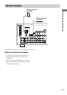
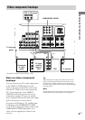
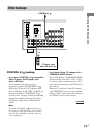
Video component hookups
To the front
panel
Camcorder
or video
game
TV monitor
DVD or LD player
Note on video component
hookups
You can connect your TV’s audio output jacks
to the VIDEO 2 AUDIO IN jacks on the
receiver and apply sound effects to the audio
from the TV. In this case, do not connect the
TV’s video output jack to the VIDEO 2
VIDEO IN jack on the receiver. If you are
connecting a separate TV tuner (or satellite
tuner), connect both the audio and video output
jacks to the receiver as shown above.
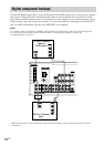
If you have a DVD player, TV, satellite tuner
or LD player with COMPONENT VIDEO
(Y, B-Y, R-Y) output jacks and a monitor with
COMPONENT VIDEO input jacks, use a
video cord (not supplied) to connect to the
receiver.
Tip
When using the S-video jacks instead of the video
jacks, your monitor must also be connected via an
S-video jack. S-video signals are on a separate bus
from the video signals and will not be output through
the video jacks.
Note
On this receiver, the component video signals are not
compatible with S-video signals or video signals.
* Except for models of area code CEL, CEK.
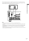
VCR
TV tuner,
satellite
tuner or
VCR