


41
Other Operations
x CONTROL A1 auto power on
(A1 AUTO POWER)
Lets you turn on the receiver automatically
when the component connected via CONTROL
A1 cords (see page 12) is turned on and the
playback is started.
When set to “OFF”, you can save the power
consumption of the receiver during standby
mode.
x CONTROL A1 auto function
(AUTO FUNCTION)
Lets you switch the function of this receiver to
the Sony components connected via CONTROL
A1 cords (see page 12) automatically when the
connected component is set to play mode.
x 2nd room speaker (2ND ROOM SP)
Lets you set whether you would output the
sound to the 2nd room or not.
x Selecting the command mode of
the remote (COMMAND MODE)
Lets you select the command mode of the
remote. Change the command mode when you
use 2 Sony receivers in the same room.
x Color of the on-screen display
(OSD)
Lets you select the color of the on-screen
display.
x OSD horizontal position (OSD
H.POSITION)
Lets you adjust the position of the on-screen
display horizontally.
x OSD vertical position (OSD
V.POSITION)
Lets you adjust the position of the on-screen
display vertically.
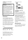
CONTROL A1 control
system
Getting Started
This section explains the basic functions
of the CONTROL A1 Control System.
Certain components have special
functions, like “CD Synchro Dubbing” on
cassette decks, that require CONTROL
A1 connections. For detailed information
regarding specific operations, be sure to
also refer to the Operating Instructions
supplied with your component(s).
The CONTROL A1 Control System was
designed to simplify the operation of audio
systems composed of separate Sony
components. CONTROL A1
connections
provide a path for the transmission of control
signals which enable automatic operation and
control features usually associated with
integrated systems.
Currently, CONTROL A1
connections
between a Sony CD player, amplifier
(receiver), MD deck and cassette deck provide
automatic function selection and synchronized
recording.
In the future, the CONTROL A1
connection
will work as a multifunction bus allowing you
to control various functions for each
component.
Notes
• The CONTROL A1 Control System is designed to
maintain upward compatibility as the Control
System is upgraded to handle new functions. In this
case, however, older components will not be
compatible with the new functions.
• Do not operate a 2 way remote control unit when
the CONTROL A1 jacks are connected via a PC
interface kit to a personal computer running “MD
Editor” or similar application. Also, do not operate
the connected component in a manner contrary to
the functions of the application, as this may cause
the application to operate incorrectly.
continued