1-17
MVE-9000 IM
1
2
3
4
5
7
6
ABCDEFGH
D3801
D3802
D3803
D3804
TP3801
TP3802
TP3803
TP3804
D3701
D3703
D3702
D3704
ND3802
ND3801
ND3902
ND3901
D3091
D3902
D3903
D3904
TP3091
TP3902
TP3903
TP3904
D1301
D504
E501
D501
D505
D502
D503
D506
TP504
TP501
TP505
TP502
TP503
TP506
D3706
D3705
D1302
D1303
CN4601
CN3503
CN3602
CN3502
S3501
S3601
CN4301
S3901
S3801
TP401
E401
TP302
E302
TP202
E202
TP301
E301
TP201
E201
TP601
G
F
E
D
C
B
A
654321
D12
D13
D10
SW1
SW2
D17
D16
D15
D14
D19
D18
CPU-DR
Module
(CPU A)
G
F
E
D
C
B
A
654321
D12
D13
D10
SW1
SW2
D17
D16
D15
D14
D19
D18
CPU-DR
Module
(CPU B)
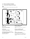
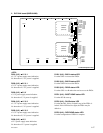
2. DVP-24A board (MKE-9040M)
<LED>
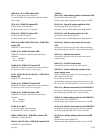
D501 (H-5) :
++
++
+1.5 V-1
+1.5 V-1 power supply status indication.
Lit when the +1.5 V-1 power is supplied.
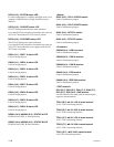
D502 (H-5) :
++
++
+2.5 V-1
+2.5 V-1 power supply status indication.
Lit when the +2.5 V-1 power is supplied.
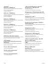
D503 (H-5) :
++
++
+3.3 V
+3.3 V power supply status indication.
Lit when the +3.3 V power is supplied.
D504 (H-5) :
++
++
+1.5 V-2
+1.5 V-2 power supply status indication.
Lit when the +1.5 V-2 power is supplied.
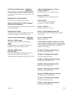
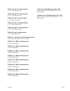
D505 (H-5) :
++
++
+2.5 V-2
+2.5 V-2 power supply status indication.
Lit when the +2.5 V-2 power is supplied.
D506 (H-5) :
++
++
+12 V
+12 V power supply status indication.
Lit when the +12 V power is supplied.
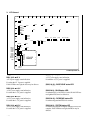
A side/Component side
D1301 (H-2) : BUS A status LED
Lit when CPU A accesses the FPGA.
D1302 (H-2) : BUS B status LED
Lit when CPU B accesses the FPGA.
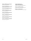
D1303 (H-2) : READ status LED
Lit when CPU A or B makes the read access to the FPGA.
D3701 (H-2) : BOOT DONE status LED
Lit when IC108 starts up.
D3702 (H-2) : DLKD status LED
Lit when the DLL (Delay Locked Loop) of the FPGA is
locked. If this LED does not light, the FPGA may be
defective.
D3703 (H-2) : RCB DONE status LED
Lit when configuration of FPGA is complete.


