


1-11
MVE-9000 IM
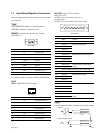
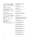
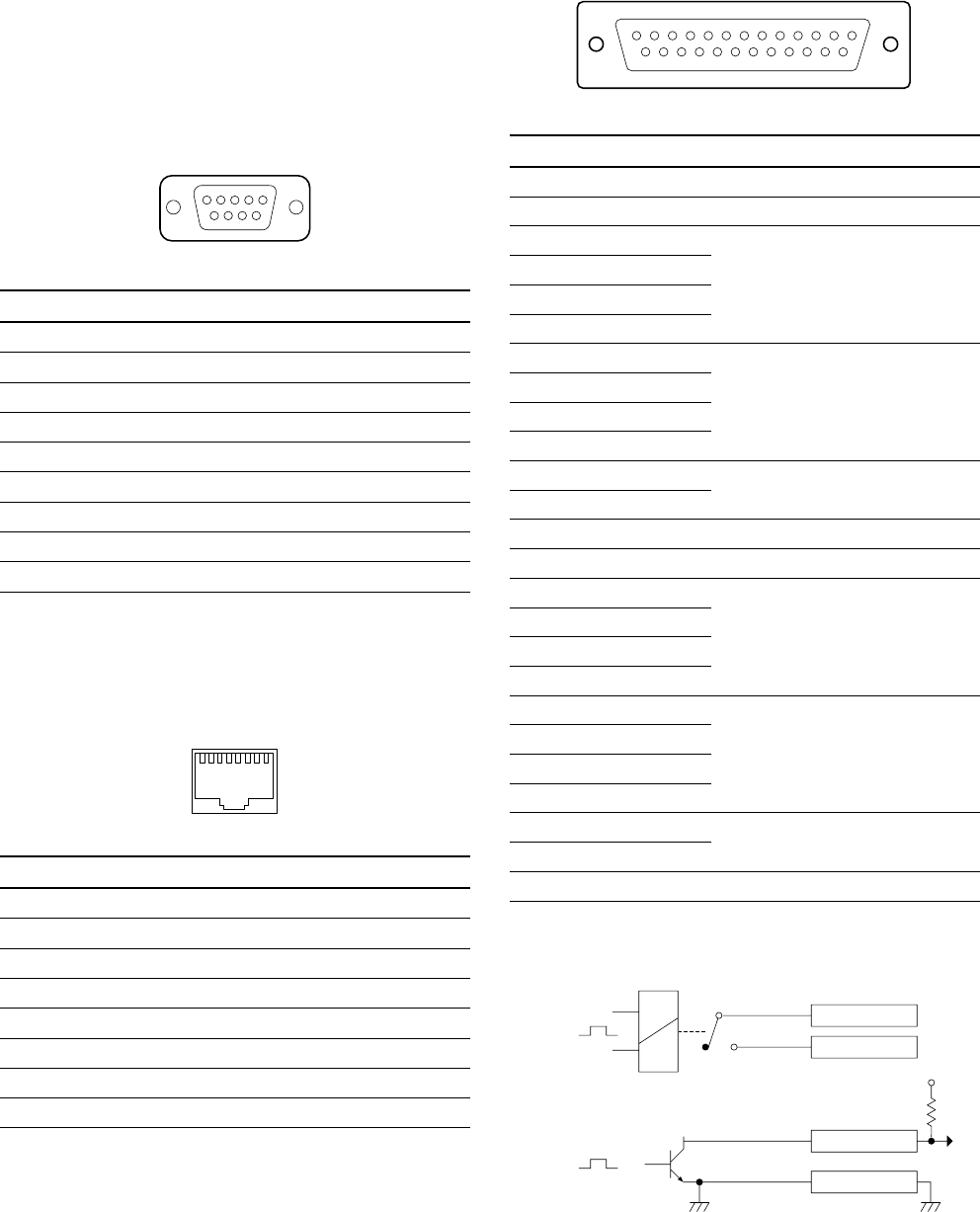
<Relay>
GPI OUT n B
GPI OUT 5-8
GPI OUT COM
<Open collector output>
n;1-4
+V
GPI OUT n A
(*2)
(*3)
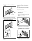
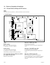
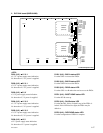
1-7. Input/Output Signals of Connectors
The input/output signals of the connectors at the rear panel
are as follows.
n
<CONTROLLER> indicates a controlling device.
<DEVICE> indicates a controlled device.
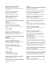
REMOTE 1-4 : RS-422A (D-sub 9-pin, Female)
<DEVICE> (*1)
Pin No. Signal Name Function
1 FG Frame ground
2TX_ Transmitted data (_)
3RX+ Received data (+)
4 GND Ground
5 _ No Connection
6 GND Ground
7TX+ Transmitted data (+)
8RX_ Received data (_)
9 _ No Connection
(*1) : Editing control unit such as BVE-9100 (EDITOR)
DATA
CTRL : 100BASE-TX, RJ-45 (8-pin)
Pin No. Signal Name Function
1TX+ Transmitted data (+)
2TX_ Transmitted data (_)
3RX+ Received data (+)
4 _ No Connection
5 _ No Connection
6RX_ Received data (_)
7 _ No Connection
8 _ No Connection
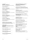
GPI, GPI2 : (D-sub 25-pin, Female)
INPUT x 8, TTL
OUTPUT x 4, relay contacts 30 V 0.1 A
(resistive load)
OUTPUT x 4, open collector 30 V rated voltage
Pin No. Signal Name Function
1 GND Ground
2 GND Ground
3 GPI IN 2 General-purpose input
4 GPI IN 4
5 GPI IN 6
6 GPI IN 8
7 GPI OUT 1B General-purpose relay output (B)
*2
8 GPI OUT 2B
9 GPI OUT 3B
10 GPI OUT 4B
11 GPI OUT 6 General-purpose open collector
12 GPI OUT 8 output
*3
13 GPI OUT COM Ground for open collector output
14 GND Ground
15 GPI IN 1 General-purpose input
16 GPI IN 3
17 GPI IN 5
18 GPI IN 7
19 GPI OUT 1A General-purpose relay output (A)
*2
20 GPI OUT 2A
21 GPI OUT 3A
22 GPI OUT 4A
23 GPI OUT 5 General-purpose open collector
24 GPI OUT 7 output
*3
25 GPI OUT COM Ground for open collector output
n
A and B of the same number constitute a pair of relay contacts.
_ EXT VIEW _
1
5
69
1
8
_ EXT VIEW _
25 14
113
_ EXT VIEW _