


1-10
MVE-9000 IM
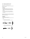
1-6. Matching Connectors and Cables
Use the following connectors, cables or equivalents when connecting cables to the unit.
Model name Panel indication Connector name Matching connector and cable
Name Sony part No.
MVE-9000 REF IN BNC, 75 Z BNC, 75 Z
EXT IN 1-4 BELDEN 8281 coaxial cable
MONI OUT 1-4
REMOTE 1-4 D-sub 9-pin, Female D-sub 9-pin, Male
Connector 9-pin, Male 1-560-651-00
*1
Junction Shell 9-pin 1-561-749-00
GPI D-sub 25-pin, Female D-sub 25-pin, Male
GPI2 Connector 25-pin, Male 1-560-904-11
*1
Junction Shell 25-pin 1-563-377-11
DATA RJ-45 modular jack
*2
__
CTRL
MKE-9020M SWITCHER A, B MDR 68-pin, Female Dedicated cable _
(Supplied accessory of MKE-9020M)
MKE-9021M IN V1-V4 BNC, 75 Z BNC, 75 Z
IN K1-K4 BELDEN 8281 coaxial cable
OUT V1-V4
OUT K1-K4
*1 : The following crimp contact is required for the plug.
AWG#18 to #22 : 1-566-493-21
AWG#22 to #24 : 1-564-774-11
AWG#24 to #30 : 1-564-775-11
*2 : Conforms to the IEEE 802.3 Ethernet100BASE-TX standards.