


1-4
MVE-9000 IM
1-4. Installing the Options
The MVE-9000-C is shipped from the factory with the
necessary option (refer to the following table) already
installed in the MVE-9000, in accordance with the speci-
fied system configuration.
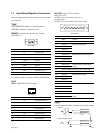
MVE-9000-C options
Model name Board configuration
Plug-in board Connector board
MKE-9020M _ CN-2357A board
MVS Interface Board Set CN-2357B board
MKE-9021M _ CN-2355A board
Input/Output Board Set CN-2355B board
MKE-9040M DVP-24A board
Advanced Effects Board
HK-PSU04 __
Power Supply Unit
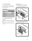
1-4-1. Installing the Plug-in Boards
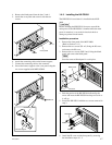
c
Be sure to turn off the POWER switch and unplug the
power cord from the wall outlet before starting the installa-
tion work.
If the installation work is started with the POWER switch
left on, it may cause electrical shock or damage of printed
circuit boards.
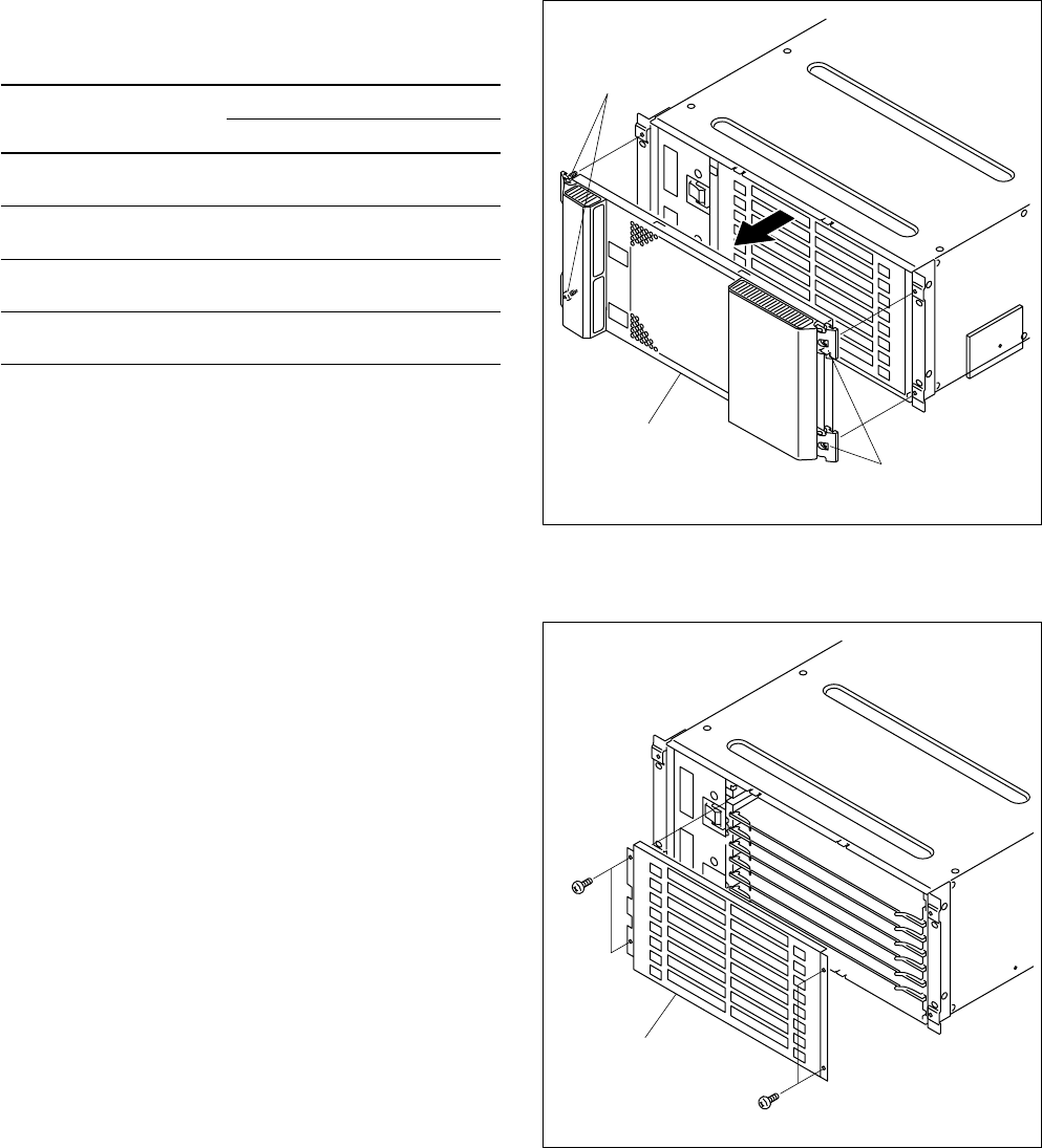
Installation procedure
1. Turn off the main power of the MVE-9000 and
disconnect the AC power cord from the wall outlet.
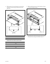
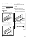
2. Loosen the four screws (with drop-safe) and remove
the front panel in the direction of the arrow.
3. Remove the four screws (B3 x 5), and remove the
“plug-in board loose-proof assembly”.
Screws
(with drop-safe)
Front panel
Screws
(with drop-safe)
B3 x 5
B3 x 5
Plug-in board
loose-proof assembly