


— 18 —
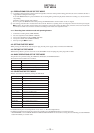
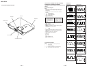
5-7. TRAVERSE ADJUSTMENT
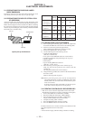
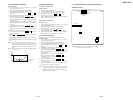
Connection :
Oscilloscope
V : 0.5 V/div
H : 10 ms/div
Input : DC mode
BD board
CN110 pin
3
(TEO)
CN110 pin
2
(VC)
Adjusting method :
1. Connect an oscilloscope to CN110 pin 3 (TEO) and CN110
pin 2 (VC) of the BD board.
2. Load a disc (any available on the market). (Refer to Note 1.)
3. Press the 0 button or ) button and move the optical pick-
up outside the pit.
4. Rotate the AMS knob and display “EFBAL ADJUST”.
5. Press the YES button and display “EFB = MO-R”.
(Laser power READ power/Focus servo ON/tracking servo
OFF/spindle (S) servo ON)
6. Rotate the AMS knob so that the waveform of the oscilloscope
becomes the specified value.
(When the AMS knob is rotated, the of “EFB= ” changes
and the waveform changes.) In this adjustment, waveform varies
at intervals of approx. 2%. Adjust the waveform so that the
specified value is satisfied as much as possible.
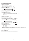
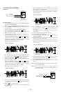
(Read power traverse adjustment)
(Traverse Waveform)
VC
A
B
Specification A = B
7. Press the YES button and save the result of adjustment to the
non-volatile memory (“EFB = SAVE” will be displayed for
a moment. Then “EFB = MO-W” will be displayed).
8. Rotate the AMS knob so that the waveform of the oscilloscope
becomes the specified value.
(When the AMS knob is rotated, the of “EFB- ” changes
and the waveform changes.) In this adjustment, waveform varies
at intervals of approx. 2%. Adjust the waveform so that the
specified value is satisfied as much as possible.
(Write power traverse adjustment)
(Traverse Waveform)
VC
A
Specification A = B
B
9. Press the YES button, and save the adjustment results in the
non-volatile memory. (“EFB = SAVE” will be displayed
for a moment.)
10. “EFB = MO-P”. will be displayed.
The optical pick-up moves to the pit area automatically and
servo is imposed.
11. Rotate the AMS knob until the waveform of the oscilloscope
moves closer to the specified value.
In this adjustment, waveform varies at intervals of approx. 2%.
Adjust the waveform so that the specified value is satisfied as
much as possible.
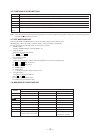
(Traverse Waveform)
VC
A
B
Specification A = B
12. Press the YES button, and save the adjustment results in the
non-volatile memory. (“EFB = SAVE” will be displayed for
a moment.)
Next “EFBAL CD” is displayed. The disc stops rotating
automatically.
13. Press the §EJECT button and remove the disc.
14. Load the check disc (MD) TDYS-1.
15. Press the YES button and display “EFB = CD”. Servo is
imposed automatically.
16. Rotate the AMS knob so that the waveform of the oscilloscope
moves closer to the specified value.
In this adjustment, waveform varies at intervals of approx. 2%.
Adjust the waveform so that the specified value is satisfied as
much as possible.
(Traverse Waveform)
VC
A
B
Specification A = B
17. Press the YES button, display “EFB = SAVE” for a moment
and save the adjustment results in the non-volatile memory.
Next “EFBAL ADJUST” will be displayed.
18. Press the §EJECT button and remove the check disc (MD)
TDYS-1.
Note 1 : MO reading data will be erased during if a recorded disc is
used in this adjustment.
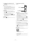
Note 2 : If the traverse waveform is not clear, connect the
oscilloscope as shown in the following figure so that it can
be seen more clearly.
Oscilloscope
330 k
Ω
10pF
BD board
CN110 pin
3
(TEO)
CN110 pin
2
(VC)