Chapter 7 Connections and
Settings
Chapter 7 Connections and Settings 127
Connections for Digital Nonlinear Editing Using
SDTI (QSDI) Interface
This unit can be connected to an ES-7 EditStation to
configure a digital non-linear editing system. Using the
SDTI (QSDI) interface, you can transfer video, audio,
timecode, and other compressed data between this unit
and the EditStation.
The unit supports ClipLink functions, enabling index
pictures recorded on tape and ClipLink log data stored
in cassette memory to be transferred to the EditStation
in an instant.
For an overview of the ClipLink function, see the appendix
“ClipLink Guide” (page 147).
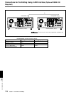
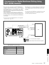
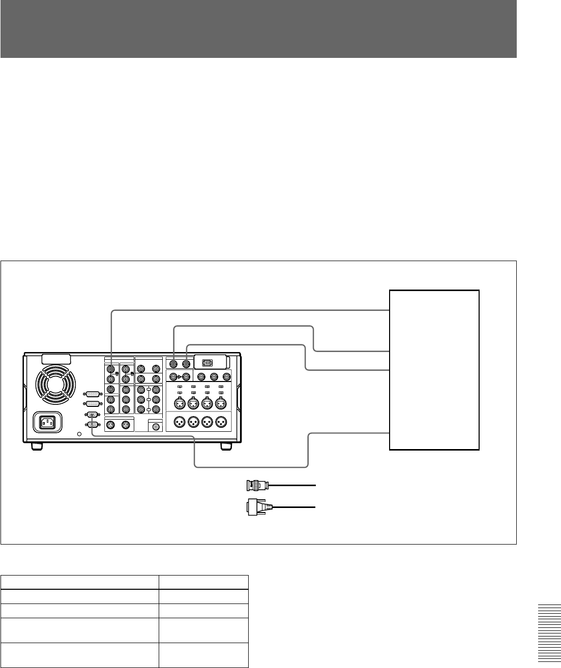
The following is a connection diagram for digital non-
linear editing system in which this unit serves as the
recorder.
For connections of the EditStation’s peripheral devices (the
control panel, the disk unit, etc.) and the player, refer to
your ES-7 Operating Instructions.
1
1
1
2
REF. VIDEO IN
REMOTE-IN
SDTI(QSDI) INPUT
SDTI(QSDI) OUTPUT
BB OUT
RECORDER
QSDI OUTPUT
QSDI INPUT
ES-7
DSR-2000/2000P (recorder)
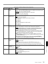
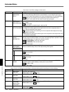
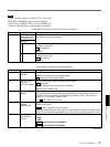
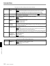
DSR-2000/2000P (recorder) settings
Control
REMOTE button
9PIN button
SDTI/i.LINK button (input selection
section)
REF.VIDEO IN 75Ω termination
switch
Setting
Lit
Lit
SDTI
ON
1 75 Ω coaxial cable (not supplied)
2 RCC-5G 9-pin remote control cable (supplied)


