<P=003>
(Continued)
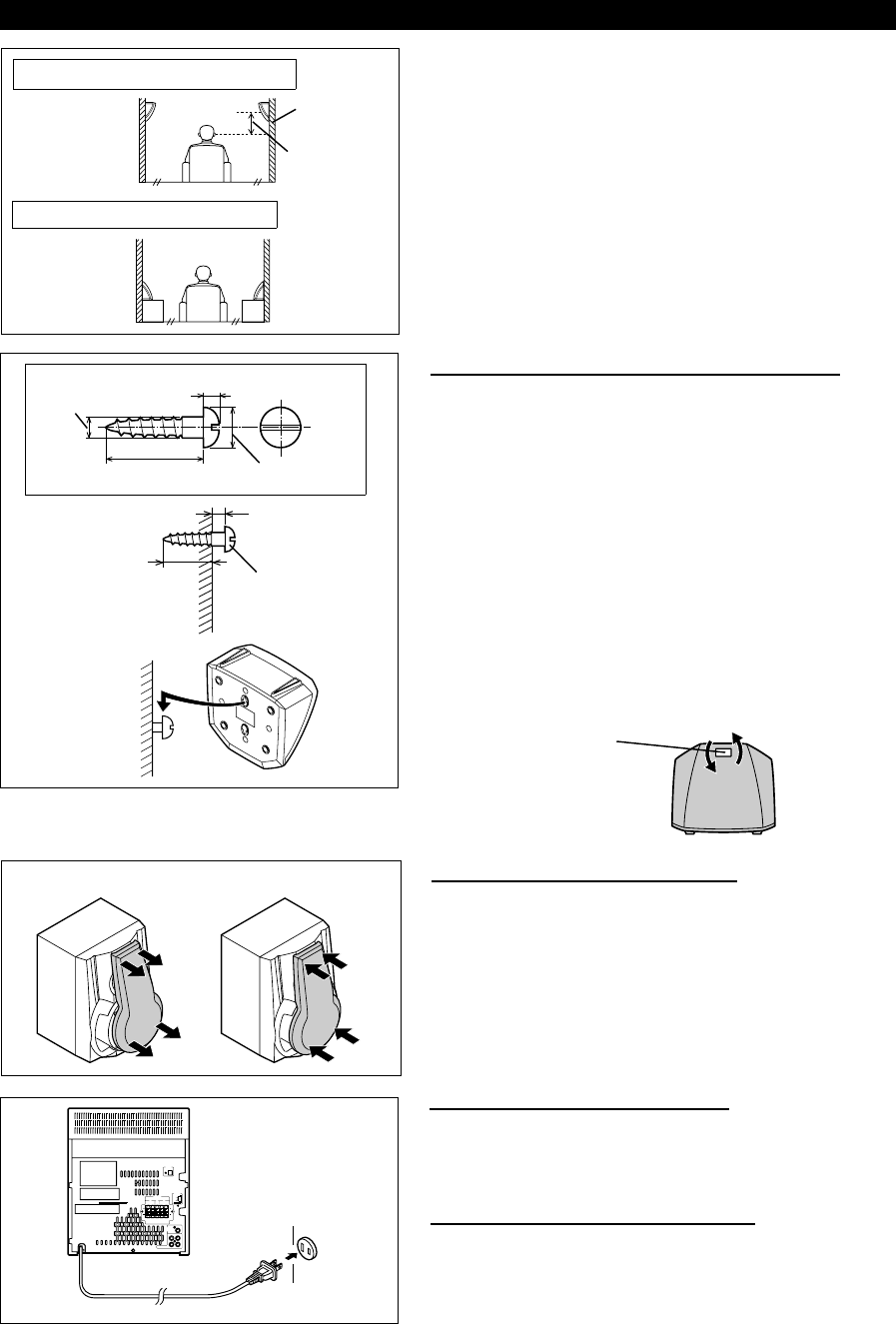
Installation of the rear speakers:
If possible, mount the rear speakers on the wall. lnstall them 23"
- 35" (60 - 90 cm) above the height of your ears when seated,
if possible.
■ To mount the rear speakers on the wall
The design of the rear speakers allows them to be hung on the
wall.
Be sure to use the type and size screw that is shown to the left.
1 Drive one screw into the wall for each speaker as shown in
the illustration.
● Make sure that both the screw and the wall can support a load
of 45 lbs. (20 kg).
● Drive the screws, so there is about a 3/16" (4 mm) space
between the wall and the head of the screw.
2 Mount the rear speaker on the wall so that the screw head
is inserted into the slot on the rear speaker.
Note:
When the rear speakers are installed vertically, the speaker
badge will be upside down.
In this case, you can adjust the badge to face the proper direction.
Just turn it by hand.
Badge
■ Removing the speaker grilles
1 Remove the lower part of the speaker grille first.
2 Remove the upper part of the speaker grille.
● The speaker grilles on the center and rear speakers are not
removable.
Caution:
When the speaker grilles are removed, the speaker diaphragms
are exposed. Make sure nothing comes into contact with the
speaker diaphragms.
■ Mounting the speaker grilles
Fit the four posts on the speaker grille into the mounting holes
and push them lightly with the palm of your hand to secure.
■ Connecting the AC power cord
● After connecting the speakers, plug the AC power cord into a
convenient AC outlet.
● Unplug the AC power cord from the AC outlet if the unit will
not be in used for a prolonged period of time.
Example: When installed on the wall
Wall
23" - 35"
(60 - 90 cm)
Example: When installed vertically
1
2
3/16" (5 mm)
1/8" (3.2 mm)
Min. 7/8" (22 mm)
3/8" (9 mm)
3/16" (4 mm)
Min. 11/16" (18 mm)
Wall surface
Wall mounting screw
Wall surface
(Front speakers only)
AC 120 V, 60 Hz
To an AC outlet
CD-PC3500(SEC) TINSE0281AWZZ
8


