


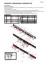
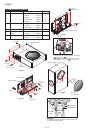
HT-SB60
2 – 2
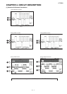
[2] Abnormal detection distinction at DEMO indicator (LED_red)
DEMO indicator Distinction Display Format
It has a case that need to Power OFF immediately after detected an abnormal condition without display any error indication due to
safety matter. In such case, a trouble point can be judged by a distinction indication at DEMO indicator which current is being supplied
during Power off.
Basically, it is decided to be distinguished which input port of the system microcomputer was detected or which communication
information was detected. Moreover, two kinds of over-voltage and drop-voltage are decided to be distinguished, and contents of
indication are decided to be changed when it is detected in the range of the A/D value in the A/D input port, for example the over-voltage,
the normality voltage, the drop-voltage of the power supply line are being monitored.
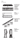
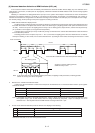
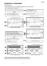
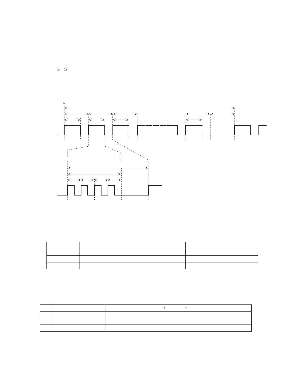
A lighting period (or flashing period) and a lights-off period are controlled as the bottom figure after the abnormal detection and
the Power off transition. It will repeat and control 1 frame of the bottom figure. (A lighting period or flash period is mentioned on the
"H" side.) 1 frame is set up as 2 sec lighting period in every 3 sec or flashing period, repeat m time, and then the last period only
(m+1) should turn off the lights. (To recognize the head position.)
A flashing period is set to one place only of No. 1 - No. m, and others are lighting period. The ‘Error Distinction No.’ is made at
which part is flashing. In other words, it is set as the ‘Distinction No.’ by looking at which number is flashing from the head of 1 frame.
m is 2
m 10, it can be set up in every model freely as long as "‘Distinction No.’ and the Abnormal Detection Table” mentioned
in two clauses are protected.
Power off transition
1 Frame
ces3ces3ces3ces3ces3
ces2 ces2 ces2 ces2
m.oN 3.oN 2.oN 1.oN tuo DEL
It becomes Error Distinction No.2 when No.2 period is flashing.
No.2 flashing period
3sec
2sec
500m 500m 500m 500m
As figure on the left, flashing period is
500ms and duty is 50%.
LED out
Note:
It can set up freely in every model the repetition period 3sec, the lighting or flash period 2sec, a flashing periodic
500ms etc. as long as it can be recognized.
Reference
System Protect1
2 Reserved
3 AMP Shutdown
Abnormal supply detection
-
AMP protection
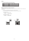
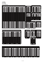
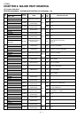
It defines the abnormal detection contents that correspond to the ‘Distinction No.’ as the bottom table in order to put in together
between the models.
It is desirable to indicate it with small ‘Distinction No.’ when it is being monitored two and more abnormal detection in one
line together using 1 port. In other words, when it is being monitored by compound 1 input. For example, it is set to
Distinction No. 1 when System Protect and AMP Protect are being monitored in 1 port.
2. Distinction No. and Abnormal Detection Table
Note:
3. For this model, abnormal detection (Power Off without error display) as the following.
Reference: This case, m = 3 and 1 frame period is 12 sec.
Abnormal Detect
Process
(1) SYSTEM PROTECT Power OFF and indicate at POWER LED ‘Distinction No.1’
- )2( Reserved
’3.oN noitcnitsiD‘ DEL REWOP ta etacidni dna FFO rewoP )3( AMP_Shutdown
Distinction No. Abnormal Detection Name
1.