


HT-SB60
8 – 1
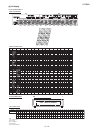
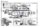
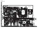
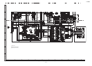
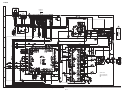
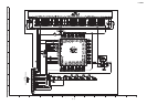
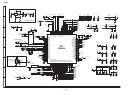
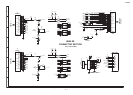
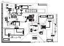
CHAPTER 8. CIRCUIT SCHEMATICS AND PARTS LAYOUT
[1] Notes On Schematic Diagram
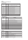
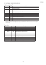
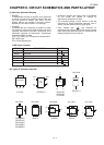
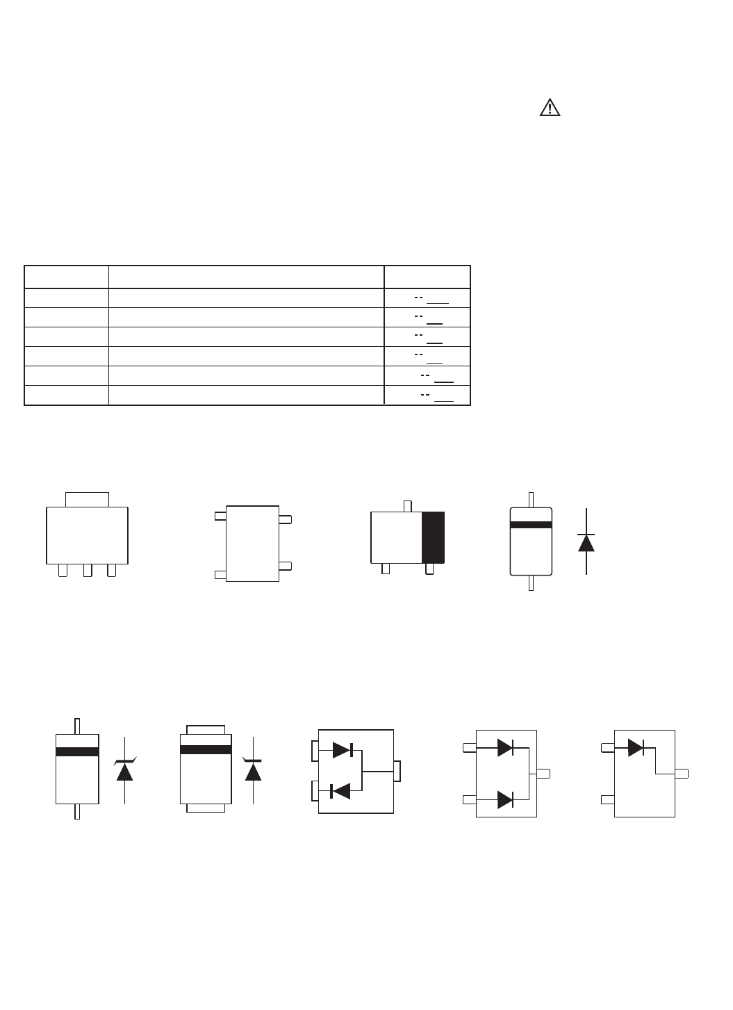
[2] Types Of Transistor And LED
••
•
Resistor:
To differentiate the units of resistors, such symbol as
K and M are used: the symbol K means 1000 ohm
and the symbol M means 1000 kohm and the
resistor without any symbol is ohm-type resistor.
Besides, the one with “Fusible” is a fuse type.
Capacitor:
To indicate the unit of capacitor, a symbol P is used:
this symbol P means pico-farad and the unit of the
capacitor without such a symbol is microfarad. As to
electrolytic capacitor, the expression “capacitance/
withstand voltage” is used.
(CH), (TH), (RH), (UJ): Temperature compensation
(ML): Mylar type
(P.P.): Polypropylene type
Schematic diagram and Wiring Side of P.W.Board
for this model are subject to change for
improvement without prior notice.
•
•
The indicated voltage in each section is the one
measured by Digital Multimeter between such a
section and the chassis with no signal given.
Parts marked with “ ” are important for
maintaining the safety of the set. Be sure to replace
these parts with specified ones for maintaining the
safety and performance of the set.
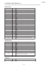
PWB Switch Location
REF. NO DESCRIPTION POSITION
SW701
SW702
SW703
ON/STAND-BY
SOURCE
PAIRING
SW704 EQ
SW705
SW706
VOLUME (-)
VOLUME (+)
OFFON
ON ON
ON ON
ONON
MINMAX
MINMAX
(1) (2) (3)
KRC102S
KRC104S
KTA1544T
B
(2)
E
(1)
C
(3)
TOP VIEW
1117Y33
DA1010++
EXA686WJ
EXA701WJ
EXA716WJ
EXA738WJ
EXA694WJ
TOP VIEW
TOP VIEW
TOP VIEW
TOP VIEW
TOP
VIEW
PST8227U
SS14++ KDS226
OUT
(1)
GND
(4)
N.C
(3)
VDD
(2)
TOP
VIEW
(3)
(2)
(1)
BAT54
TOP VIEW
(1)
(2)
(3)
BAS16
TOP VIEW
(1)
(2) NC
(3)