


4
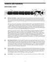
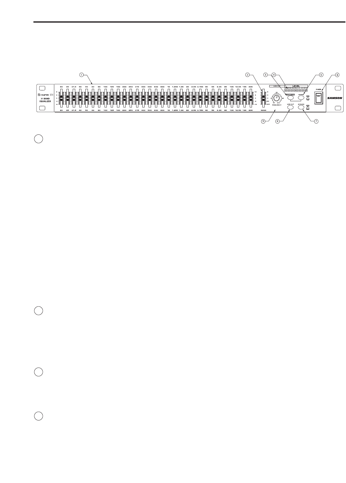
1 Equalizer level sliders - Independent Equalizer sliders are provided for each frequency area (The S
curve 131 provides 31 frequency areas).Calibration markings on either side of each Equalizer slider
allow you to cut or boost each frequency area. As described below, the exact action of the Equalizer
sliders depends upon the setting of the Range switch as well as the setting of the Cut Only switch (see
#3 and #5.
When the Cut Only switch is not pressed in: When an equalizer slider is at its center detented “0” position,
the frequency area is unaffected (that is, there is no boost or cut). When moved all the way up (to the
“+12 dB”) position, the frequency area is boosted by 12 dB (if the corresponding Range switch is not-
pressed in) or 6 dB (if the corresponding Range switch is pressed in). When moved all the way down
(to the “-12 dB” position), the frequency area is attenuated by 12 dB (if the corresponding Range switch
is not pressed in) or 6 dB (if the corresponding Range switch is pressed in).
When the Cut Only switch is pressed in: When an equalizer slider is at its top-most position, the frequency
area is unaffected (that is, there is no boost or cut), as indicated by the blue “0 dB” label. As the
Equalizer slider is moved down, the frequency area is attenuated. As indicated by the “-6 dB” label,
when the Equalizer slider is at its center detented position, the frequency area is attenuated by 6 dB (if
the corresponding Range switch is pressed in) or 12 dB (if the corresponding Range switch is not
pressed in). When moved all the way down (as indicated by the blue “-24 dB” label), the frequency area
is attenuated by 12 dB (if the corresponding Range switch is pressed in) or 24 dB (if the corresponding
Range switch is not pressed in).
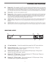
2 Main Output level slider - Use this to adjust the output level of signal leaving the S curve 131 via its
rear-panel output connectors (see C and D on page 5 for more information). When the main slider is at
its center detented “0” position, the corresponding output signal is at unity gain (that is, there is no level
cut or boost). When the main slider is moved all the way up (to the “+6 dB”) position, the output signal
is boosted by 6 dB. When a Level slider is moved all the way down (to the “∞” position), the output sig-
nal is infinitely attenuated (that is, there is no signal). Note that the Main level slider is deactivated
when the S curve 131 is in Bypass mode (see #7).
3 CUT ONLY switch - When pressed in, the LED switch lights and all the Equalizer sliders serve to attenu-
ate their frequency areas only (there is no boost) by up to 6 or 12 dB, depending upon the setting of the
RANGE switch (see #5 below). The Cut Only switch should be used when you need to notch out cer-
tain frequencies in order to reduce feedback or “ring out” a room. See the “Using the S curve 131 to
remove feedback” section in this manual (page 14) for more information.
4 LEVEL METER - This eight segment LED bar VU meter displays the Input Level from –30dB to +18dB.
Controls and Functions
FRONT PANEL LAYOUT