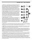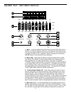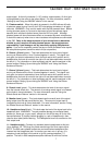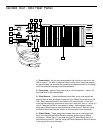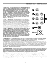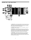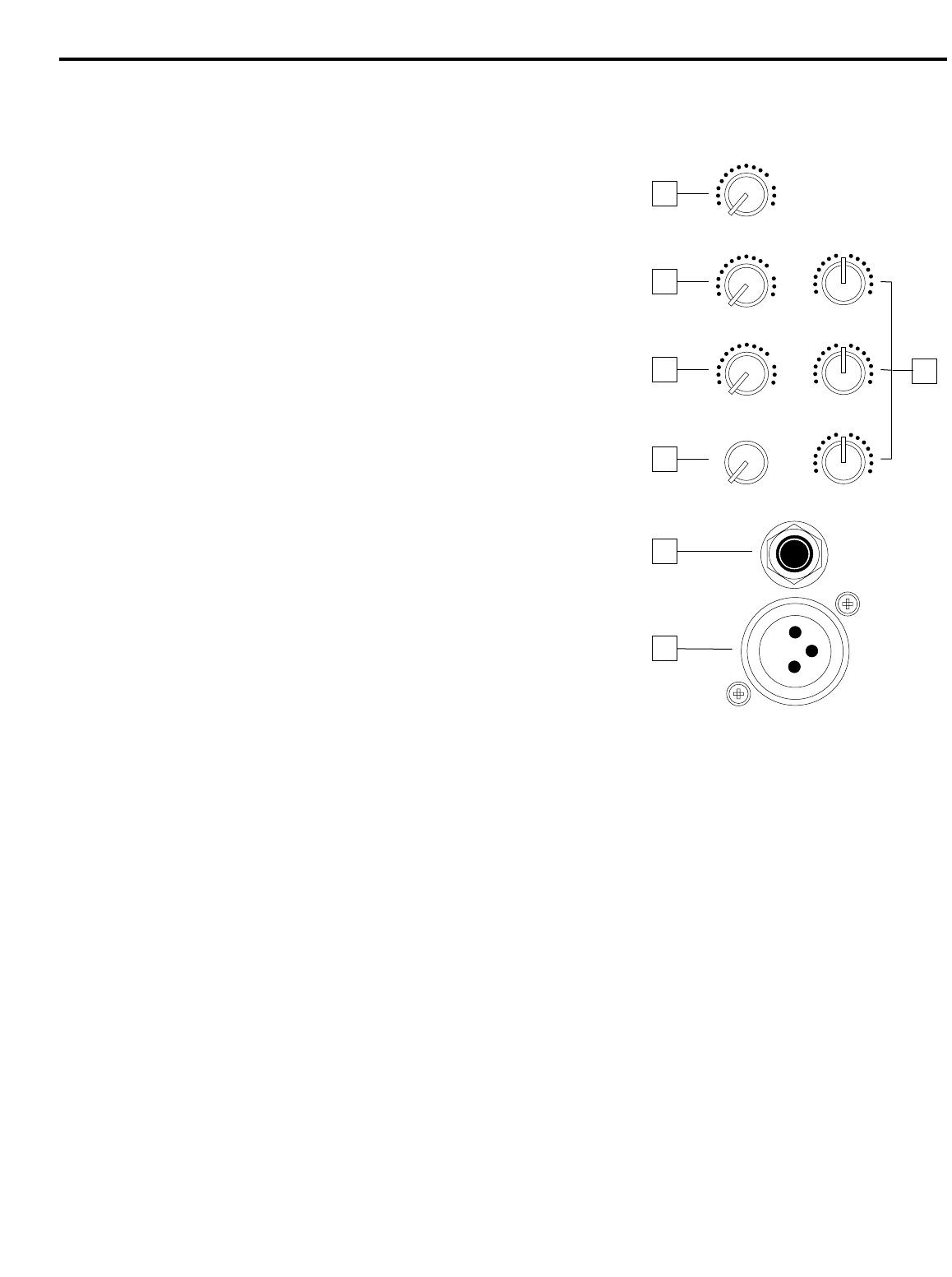
1: Level (white) - This knob determines the final signal level being sent by
a channel to the main speaker outputs as well as to Effect send 1 (see #2
below). In practice, this will be used to adjust the levels of the various
signals being blended together by the S63. The “0” position indicates
unity gain (no level attenuation or boost). Moving the knob counterclock-
wise from “0” (towards the “∞” position) causes the signal to be attenuated
(when fully counterclockwise, the signal is attenuated infinitely—in other
words, there is no sound). Moving it clockwise from the “0” position
(towards the “+15” position) causes the signal to be boosted by as much
as 15 db. For best signal-to-noise ratio, all channel level controls should
be kept at or near the 0 level.
2: Effect 1 / Monitor (gray) - This knob allows you to send signal from
one or more channels to the S63’s Monitor output or to an external signal
processor connected to the Effect Send 1 output jack on the rear panel.
This effects send is pre-fade; that is, the level of the signal is determined
solely by the channel’s input trim, and is unaffected by its EQ settings and
the position of its level control. At the 0 position, the signal is routed with
unity gain (that is, no boost or attenuation). As each Effect 1 / Monitor
knob is turned clockwise from the 0 position, the signal is boosted; as it is
turned counterclockwise from the 0 position, the signal is attenuated.
3: Effect 2 / Reverb (gray) - This knob allows you to send signal from one
or more channels to the S63’s internal reverb unit or to an external signal
processor connected to the Effect Send 2 output jack on the rear panel.
This effects send is post-fade; that is, the level of the signal is determined
by the channel’s input trim, its EQ settings, and the position of its level
control. At the 0 position, the signal is routed with unity gain (that is, no
boost or attenuation). As each Effect 2 / Reverb knob is turned clockwise
from the 0 position, the signal is boosted; as it is turned counterclockwise
from the 0 position, the signal is attenuated.
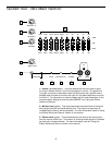
4: Input trim (black) - This knob determines the input level of the connected mic or line signal. Continuously adjustable
from +4 db to -40 db, the input trim is at unity gain (no boost or cut) when set to the “0” position. The input signal is
boosted when the trim is turned to the right of “0” and attenuated when turned to the left of “0.”
5: Equalizer (blue) - These knobs determine the amount of boost or attenuation in each of three frequency areas. The
high and low frequency knobs provide 15 db of cut or boost at 10 kHz and 80 Hz, respectively, with shelving-type control.
The middle frequency knobs provide 12 db of cut or boost at 1 kHz, with a bell (peaking) curve. A center detent in each
knob (at the 12 o’clock position) indicates no boost or attenuation (that is, flat response). As each knob is turned clock-
wise from the center detent position, the frequency area is boosted; as it is turned counterclockwise from the center
detent position, the frequency area is attenuated.
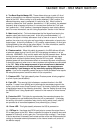
6: Line input connector - Connect line-level sources (such as synthesizers, drum machines, CD players, tape decks, or
effects processors) to any of the S63’s six channels using this electronically balanced 1/4” jack (balanced or unbalanced
signals can be accepted here). WARNING: Do not connect a channel’s line input if you already have something con-
nected to its microphone input; each channel is designed to accept only one source or the other.
7: Mic input connector - Connect a microphone to any of the S63’s six channels using this standard XLR jack. This
jack is intended to accept signal from low-level, low-impedance mics but can also be used to accept signal from other
sources (such as direct injection boxes) if the Input Trim control is turned down. WARNING: Do not turn the S63’s
Phantom power on if signal sources other than microphones are connected to any of these inputs. Also, do not connect a
channel’s microphone input if you already have something connected to its line input; each channel is designed to accept
only one source or the other.
11
Guided Tour - S63 Channel
-12
+12
1 kHz
0
-15
+15
HIGH
0
-15
+15
LOW
0
+15
LEVEL
0
+10
EFF1 MON
0
+4
-40
TRIM
0
10
+10
EFF2 REV
0
LINE
MIC
−∞
−∞
−∞
1
2
3
5
7
6
4


