


9
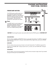
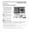
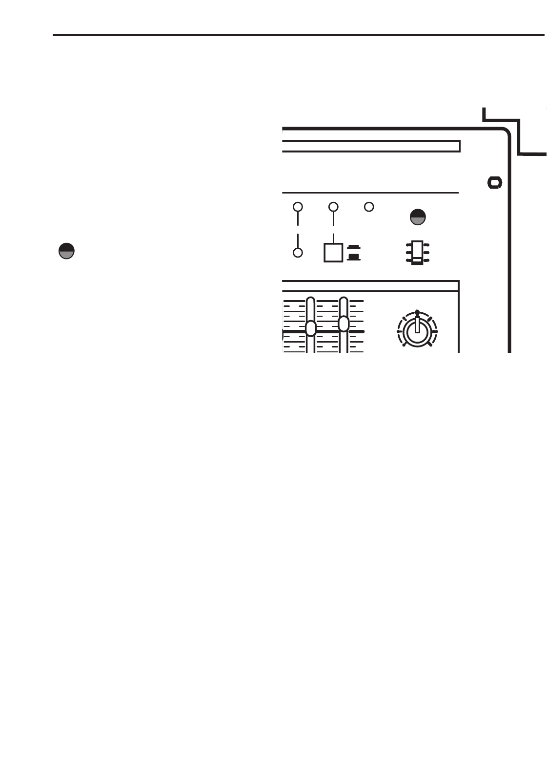
POWER AMP SECTION
The PA324’s power amplifier section can
be configured to operate several ways
depending on whether you need MAIN plus
MONITOR amplifiers to power your speak-
ers, or if you just need more power for the
MAIN speakers. The section below
describes the PA324 power amp modes.
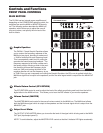
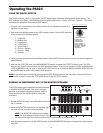
Mode
The MODE switch is used to select one of
three different operating modes, MAIN-
MONITOR, MAIN-MAIN and MAIN-
BRIDGE. The following is a description of
each of the POWER operating modes:
CAUTION! Only change the power amp mode switch when the PA324’s power is SWITCHED OFF!
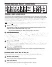
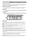
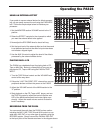
MAIN-MONITORS
With this setting, the MAIN and MONITOR sections can be used independently. The MAIN bus signal will
be sent from the POWER AMP 1 A/B jacks, and the MONITOR bus signal will be sent from the POWER
AMP 2 A/B jacks.
MAIN-MAIN
With this setting, the two power amp channels can be used independently. The MAIN bus signal will be
output from the POWER AMP 1 A/B jacks (Rear Panel 1), and also, from the POWER AMP 2 A/B jacks
(Rear Panel 1).
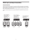
MAIN-BRIDGE
With this setting, the two power amp channels (A and B) will be connected in bridge mode. Only the MAIN
bus signal will be output from the BRIDGE jack.
5
0
10
NN
0dB
+12dB
PA324
PHANTOMCLIP
POWER
ON
OFF
MODE
MAIN MAIN
MONITOR
MAIN
MAIN
BRIDGE
DSP24
DIGITAL EFFECTS
BIT
19
19
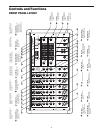
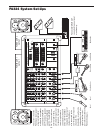
Controls and Functions
FRONT PANEL CONTROLS