15
HOW - Cutting Wall/Ceiling Openings for Speakers
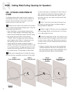
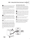
Carefully score the penciled outline of the template
with a sharp utility knife to avoid chipping paint or tear-
ing wallpaper. Then use a keyhole/drywall saw to cut
along the scored line. Make sure you don’t make it any
larger than the marked outline.
• If you’re dealing with lath and plaster or thick panel-
ing, you’ll need to use a different technique. Using a
1-inch flat bit, drill holes at the inside corners of the
pencil outline. Be careful not to drill beyond the out-
line. Then use a fine-toothed keyhole saw or a hack-
saw blade and with VERY slow strokes, saw through
the surface.
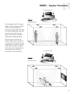
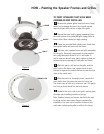
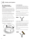
Temporarily place the speaker’s outer mounting
frame into the cut-out to insure that it fits properly. It’s
okay if the hole is slightly larger than the inner lip of the
frame, as it will be covered by the frame’s outer bezel.
Actual installation must wait until after you’ve routed the
speaker wires.
Repeat steps 1 through 7 for the other speaker.
When installing speakers in an internal (non-insulated)
ceiling, we recommend you place standard household
fiberglass insulation (without a vapor barrier) within the
wall cavity. This generally improves the sound produced
by the speakers and slightly reduces the transmission of
sound to the adjacent room. There may not be room to
place insulation directly behind the woofer magnet, but
you can fill the rest of the cavity, or as far as you can
access.
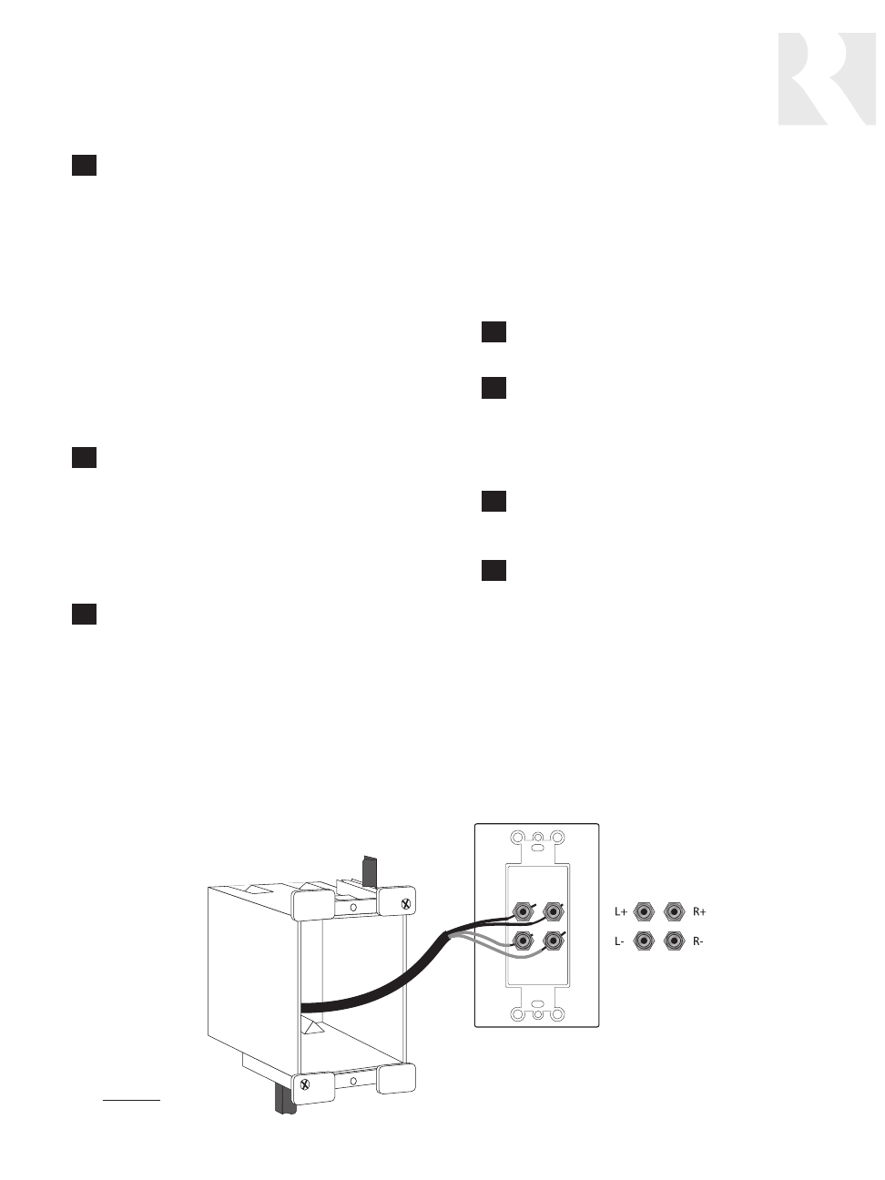
JUNCTION BOX INSTALLATION
The following steps outline how to bring wires to the
amplifier location. The speaker wires will be terminated
in an outlet box attached to a stud (during construction),
or a retrofit junction box or low-voltage mounting ring
that clamps to the wallboard. You will cut a hole for the
outlet box, run the wires through, and install the box.
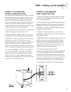
Determine the wire exit location on the wall. Identify
the nearest stud using the stud finder techniques above.
Using the outlet box as a template, trace a box just
to the left or right of the nearest stud. Using the same
1-inch drill bit as before, drill a 1-inch hole in the center
of the pencil outline you have drawn.
Insert a bent wire into the hole and probe to the
left and right to determine installation clearance.
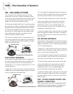
Install the retrofit junction box and cover it with an out-
let plate which has connections for the speaker wire termi-
nations. For your convenience, a full line of Russound
PlateMate™ connection systems such as the PlateMate
BP10D is available from your Russound dealer.
4
3
2
1
8
7
6
Figure 9


