


Q-750i Series Installation/Operation Manual xv
1List of Figures
PRE
L
IMINAR
Y
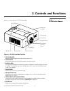
2-1. Q-750i Front/Side/Top View .........................................................................................5
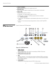
2-2. Q-750i Rear Panel........................................................................................................6
2-3. Q-750i Remote Control ................................................................................................8
3-1. Estimating Throw Distance .........................................................................................14
3-2. Projector Placement ...................................................................................................15
3-3. Vertical Lens Shift (Example Only)...............................................................................16
3-4. Horizontal Lens Shift (Example Only)...........................................................................17
3-5. Folded Optics.............................................................................................................18
3-6. Q-750i/CineWide with AutoScope Motor Assembly....................................................20
3-7. Q750i with Ceiling Mount Adapters/Projector Stands .................................................22
3-8. AutoScope Lens Motor Installation .............................................................................23
3-9. Q-750i/CineWide with Rainier II/McKinley (Cylindrical) Lens Base Plate -
Exploded View ...........................................................................................................24
3-10. HDMI/DVI Source Connections ................................................................................27
3-11. RGB Connections ....................................................................................................28
3-12. Component Video Connections................................................................................29
3-13. Composite and S-Video Connections.......................................................................30
3-14. RS-232 Control System Connection.........................................................................31
3-15. Connecting 12-Volt Trigger Outputs .........................................................................32
3-16. External IR Receiver Connection...............................................................................33
3-17. Anamorphic Lens Mounting Assembly - Exploded View ...........................................36
3-18. Attaching the Anamorphic Lens to the Lens Ring .....................................................37
4-1. Q-750i OSD Menu Structure ......................................................................................45
4-2. Q-750i Main Menu......................................................................................................46
4-3. Typical PLUGE Pattern for Adjusting Brightness .........................................................51
4-4. Typical Gray Bar Pattern for Adjusting Contrast ..........................................................51
4-5. Typical Test Pattern for Adjusting Sharpness..............................................................52
4-6. Overscan Examples....................................................................................................53
4-7. Input Select Sub-Menu...............................................................................................54
4-8. Q-750i Advanced Menu .............................................................................................55
4-9. RGB Adjust Sub-Menu...............................................................................................58
4-10. Fine Sync Sub-Menu ................................................................................................59
4-11. PCE Sub-Menu ........................................................................................................60