


Controls and Functions
Runco LS-7 Installation/Operation Manual 7
PRE
L
IMINAR
Y
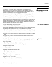
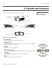
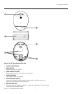
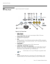
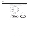
Figure 2-2. LS-7 Rear/Bottom/Top View
1. RUNCO LOGO BADGE
2. REAR COVER
Remove to access connectors.
3. LAMP MODULE COVER
Remove this cover to access the lamp compartment.
4. CABLE OPENING
Pass cables through this opening.
5. CEILING MOUNT HOLES
Use these to attach the ceiling bracket to the projector. Use M4 screws with a
maximum screw depth of 10
mm (0.39 inch).
6. ADJUSTABLE FEET
Use these when the projector is installed in a table-top configuration to level the image
and/or adjust the projection angle.
2
6
3
1
5
4