6
Rear Panel Connections
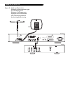
The RT-02 provides rear panel connections for
audio line level output, an FM antenna, an AM
antenna, a 12V Trigger, a remote IR sensor,
and AC power input.
NOTE: Do not plug any system component into
an AC source until system hookup is complete
and you are confident that all component-to-
component connections have been properly
made.
RCA Outputs
Line level RCA audio outputs send a fixed-level
stereo signal from the RT-02 to your pream-
plifier, system controller, or integrated amplifier.
Use a standard RCA audio cable to connect
the LEFT OUTPUT jack to the left channel tuner
input on your system controller and the RIGHT
OUTPUT jack to the right channel tuner input
on your system controller.
AM Loop Antenna
The RT-02 includes a loop antenna to receive
AM radio signals. Remove this antenna from
the box and locate it near the RT-02.
Connect the 300 ohm twin-conductor wire from
the loop antenna to the pair of screw termi-
nals labeled AM LOOP, attaching one wire
to each terminal. It does not matter which wire
attaches to which terminal, but make sure that
the connections are solid and that the two wires
do not touch.
You may need to rotate or otherwise reorient
the antenna to find the best position.
NOTE: To use an outdoor antenna, connect
its 300 ohm twin-conductor wire to the G and
AM terminals in place of the loop antenna,
only after a professional contractor has in-
stalled the antenna system in accordance with
local electrical codes.
FM Antenna
The RT-02 is supplied with a T-shaped indoor
FM antenna. Remove this antenna from the
box and connect its attached coax F-type plug
to the FM antenna connector on the RT-02. For
best reception, unfold the T-shaped antenna.
Eyelets at both ends of the T allow tacking the
antenna to a wall, if desired. Experiment with
positioning for best reception.
NOTE: To use an outdoor antenna, connect
its 75 ohm coax lead wire to the FM connec-
tor in place of the indoor wire antenna, only
after a professional contractor has installed
the antenna system in accordance with local
electrical codes. In the USA, you will need to
use the supplied F-type converter to connect
the 75 ohm coax cable to the antenna input.
AC Input
Your RT-02 is configured at the factory for the
proper AC line voltage in the country where
you purchased it (115 volts AC at 60Hz in
the USA and 230 volts AC at 50Hz in Europe).
The AC line configuration is noted on a de-
cal on the back of your unit. Make sure that
your unit is configured properly for your AC
line voltage.
Plug the supplied cord into the AC INPUT
receptacle on the back of the unit. Once all
other rear panel connections are completed,
plug the power cord into an AC wall outlet
or switched AC outlet on another system com-
ponent.
12V TRIGGER Connection
The RT-02 can be activated by a 12 volt trig-
ger signal from a Rotel preamplifier.
The trigger input accepts any control signal
(AC or DC) ranging from 3 volts to 30 volts.
When a cable is connected to the input and
a trigger signal is present, the tuner is acti-
vated. When the trigger signal is interrupted,
the tuner goes into standby mode. The front
panel indicator light remains lit, but the dis-
play goes dark and the unit will not operate.
NOTE: When using the 12V Trigger feature,
leave the POWER button in the ON position.
EXT REMOTE IN Jack
This 3.5mm mini-jack receives command codes
from industry-standard infrared receivers
(Xantech, etc.) via hard-wired connections. This
feature could prove useful when the unit is
installed in a cabinet and the front-panel sensor
is blocked. Consult your authorized Rotel dealer
for information on these external repeaters and
the proper wiring of a jack to fit the mini-jack
receptacle.
Basic Operating Controls
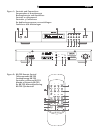
The following explanations will help you get
familiar with the features and controls. When
a function is available on both the front panel
and the remote, a number (see front panel
illustration) and a letter (see remote control
illustration) are shown in the instructions. For
example, to change from the AM to FM band,
you can either press the front panel button or
use the button on the remote. When only one
identifier appears, that control is available only
on the front panel or the remote, but not both.
NOTE: Controls used for tuning the AM/FM
receiver are described in the next sections of
this manual.
Power Button and
Power LED
The POWER button is located on the front panel
of the RT-02 and is not duplicated on the re-
mote control. Push the button IN to turn the
unit on. The LED above the switch and the front
panel display will light up. Push the button
again (returning it to the OUT position), to turn
the unit off.
NOTE: If you are using a switched outlet on
another component to power the RT-02 or if
you are using the 12 volt trigger feature, leave
the POWER switch in the ON position.
Remote Sensor
This front panel sensor receives infrared sig-
nals from the remote control. Make sure you
do not accidentally block this sensor with cables
or accessories.
RT-02 AM/FM Stereo Tuner


