


13
Unpacking
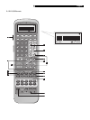
Remove the unit carefully from its packing. Find
the remote control and other accessories. Save
the box as it will protect the RSP-1098 if you
move or need to return it for maintenance.
Placement
Place the RSP-1098 on a solid, level surface
away from sunlight, heat, moisture, or vibra-
tion. Make sure that the shelf can support the
weight of the unit.
Place the RSP-1098 close to the other com-
ponents in your system and, if possible, on its
own shelf. This will make initial hookup, and
subsequent system changes easier.
The RSP-1098 can generate heat during nor-
mal operation. Do not block ventilation open-
ings. Allow a minimum of 10 cm (4 inches)
of unobstructed space around the unit. If in-
stalled in a cabinet, make sure that there is
adequate ventilation.
Don’t stack other components or objects on
top of the RSP-1098. Don’t let any liquid fall
into the unit.
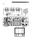
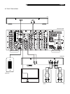
CONNECTIONS
Although, the RSP-1098’s rear panel looks
daunting, connecting the unit to your system
is straightforward. Each of the source compo-
nents in the system are connected to the
RSP-1098 inputs with a pair of standard RCA
cables for analog audio, a video connection
(composite, S-Video, or Component Video),
and an optional digital audio cable (coax or
optical).
NOTE
: Surround formats like Dolby Digital and
DTS are digital formats and the RSP-1098
can only decode them when a digital input
signal is available. For this reason, you should
always connect your DVD player’s digital
outputs to the RSP-1098, using either the op-
tical or coax inputs.
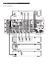
The outputs of RSP-1098 are sent to the power
amplifier(s) with standard RCA cables from
preamp audio outputs. The video signal from
the RSP-1098 is sent to the TV monitor using
composite video, S-Video, or Component Video
connections.
In addition, the RSP-1098 has MULTI input con-
nections for a source component that does its
own surround decoding, remote IR sensor
inputs, and 12V trigger connections for remote
turn-on of other Rotel components.
NOTE
: Do not plug any system component
into an AC source until all connections have
been properly made.
Video cables should have a 75 ohm imped-
ance. The S/PDIF digital audio interface stan-
dard also specifies a 75 ohm impedance and
all good digital cables adhere to this require-
ment. Do NOT substitute conventional audio
interconnect cables for digital or video signals.
Standard audio interconnects will pass these
signals, but their limited bandwidth reduce per-
formance.
When making signal connections, connect LEFT
channels to LEFT channel jacks and RIGHT chan-
nels to RIGHT channel jacks. All RCA-type
connections on the RSP-1098 follow these stan-
dard color codes:
Left channel audio: white RCA jack
Right channel audio: red RCA jack
Composite video: yellow RCA jack
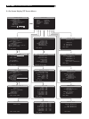
NOTE
: Each source input must be properly
configured using the INPUT SETUP menu of
the OSD menu system. We recommend go-
ing to this menu after connecting each source
to configure it as desired. See Input Setup of
the Setup section for information.
Analog Audio Inputs &
Outputs
The following connections are used for con-
necting analog audio signals to and from the
RSP-1098. See the
Making Connections
topic
for specific instructions on connecting each type
of component.
NOTE
: Normally, the RSP-1098 converts ana-
log inputs to digital signals. All of the digital
processing is available including bass man-
agement, digital crossovers, speaker level and
delay settings and a number surround mode
options including 2-ch stereo, Dolby Pro Logic
II, etc. Alternatively, there is an analog by-
pass surround mode that routes 2-ch analog
inputs directly to the Volume control and
preamp outputs, bypassing the digital pro-
cessing entirely for pure analog stereo.
CD Inputs
A left/right pair of RCA analog audio inputs
for connecting a CD player.
Tuner Inputs
A left/right pair of RCA analog audio inputs
for connecting an AM/FM tuner.
TAPE Inputs
A pair of RCA inputs, labeled TAPE IN, for
connecting the left/right analog audio signals
from an audio tape deck or recording device.
TAPE Outputs
A pair of RCA inputs, labeled TAPE OUT, for
sending left/right line level analog audio sig-
nals for recording on a tape deck or record-
ing device.
NOTE
: These outputs should be connected to
the inputs of the same tape deck connected
to the TAPE IN inputs.
English