


15
English
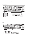
Cable, Satellite, or HDTV Tuner
l; z
See Figure 8
TV tuner connections can be made to the VID
-
EO 1, 2, 3, or 4 inputs.
Connect the left and right analog outputs from
the TV tuner to the left and right audio IN jacks
of the desired VIDEO 1–4 input.
Connect a composite video cable from the out
-
put of the TV Tuner to the video IN jack.
Audio Recorder k
See Figure 7
Connect the left and right analog outputs from
an audio tape deck to the TAPE IN jacks (left
and right).
Connect the left/right TAPE OUT jacks to the
left/right record inputs on the audio tape
deck.
No video connections are required for an au
-
dio recording device.
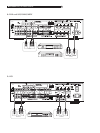
VCR l;
See Figure 9
VCR connections can be made to the VIDEO 1
or VIDEO 2 inputs and outputs.
Connect a composite video cable from the
video output of the VCR to the desired VID
-
EO 1 or 2 input.
Connect a composite video cable from the video
OUT jack to the VCR video record input.
Connect the left and right analog outputs from
the VCR to the left/right audio IN jacks for the
VIDEO 1 or 2 input selected above.
Connect the left and right audio OUT jacks to
the analog audio record inputs on the VCR.
Phono Turntable yh
See Figure 6
Connect the left and right audio output cables
of a turntable to the left/right RCA jacks la
-
beled PHONO on the RX-1052. Connect the
ground wire from your turntable to the phono
ground lug, labeled GND.
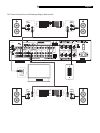
TV Monitor p
See Figure 5
Connect the TV MONITOR
output to the cor-
responding input on your television monitor,
using a composite video cable.
Speakers [
See Figure 5
There are two sets of binding post connec
-
tions (one pair for SPEAKERS A and one for
SPEAKERS B) which accept bare wire, spade
lugs, or banana plug connectors (in some
markets).
NOTE: The combined speaker impedance
must be a minimum of 4 ohms. If you are
driving just one pair of speakers (A or B
connections), use speakers with a nominal
impedance of 4 ohms or higher. If you are
driving two pairs of speakers (A and B) si
-
multaneously, use speakers rated at 8 ohms
or higher.
Each pair of connectors is color-coded for po
-
larity: red for positive and black for negative.
Speakers and speaker wire are also marked
for polarity. For proper performance, you must
maintain this polarity at all speaker connec
-
tions. Always connect the positive terminal of
each speaker to the corresponding red speak
-
er terminal on the RX-1052 and the negative
speaker terminal to the corresponding black
connector on the RX-1052.
Route the wires from the RX-1052 to the speak-
ers. Leave enough slack so you can move the
components to allow access to the speaker
connectors. If you are using banana plugs,
connect them to the wires and then plug them
into the binding posts. The collars of the bind
-
ing posts should be screwed in all the way
(clockwise). If you are using terminal lugs,
connect them to the wires. If you are attach
-
ing bare wires directly to the binding posts,
separate the wire conductors and strip back
the insulation from the end of each conductor.
Be careful not to cut into the wire strands. Un
-
screw the binding post collars. Place the con
-
nector lug or the twisted bare wire through the
hole in the binding post shaft. Turn the collars
clockwise to clamp the connector lug or wire
firmly in place.
NOTE:
Be sure that no loose wire strands can
touch adjacent wires or connectors.
Connecting one pair of speakers:
1. Connect the right speaker to the binding
posts labeled SPEAKERS A RIGHT.
2. Connect the left speaker to the binding
posts labeled SPEAKERS A LEFT.
Connecting a 2nd pair of speakers:
1. Connect the right speaker to the binding
posts labeled SPEAKERS B RIGHT.
2. Connect the left speaker to the binding
posts labeled SPEAKERS B LEFT.
NOTE: Installers can make use of the
RX-1052’s remote speaker switching func
-
tion to program a learning remote control to
switch the speakers on or off as desired.