


8
RB-1552 / RB-1582 Stereo Power Amplifier
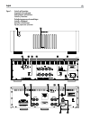
12V Trigger Input and Output
4
The jack labeled IN is for connecting the 3.5mm Plug/Cable carrying
a +12 volt trigger signal to turn the amplifier on and off. To use this
feature the toggle switch must be set to the ON position. This input
accepts any control signal (AC or DC) ranging from 3 volts to 30 volts.
The jack labeled OUT is for connecting another 3.5mm plug/cable
to provide a 12V trigger signal to other components. The 12V output
signal is available whenever a +12 volt trigger signal is applied to the
IN connector.
Protection Circuitry
2
The RB-1552 and RB-1582 feature thermal and over-current protection
circuits that protect against potential damage in the event of extreme
or faulty operating conditions. Unlike many designs, these protection
circuits are independent of the audio signal and have no impact
on sonic performance. Instead, the protection circuits monitors the
temperature of the output devices and the current they are handling
and shuts down the amplifier if operating conditions exceed safe
limits.
Most likely, you will never see this protection circuitry in action.
However, should a faulty condition arise, the amplifier will stop
playing and the LED indicator on the front panel will light up.
If this happens, turn the amplifier off, let it cool down for several
minutes, and attempt to identify and correct the problem that caused
the protection circuitry to engage. When you turn the amplifier back
on, the protection circuit will automatically reset and the indicator LED
should go out.
In most cases, the protection circuitry activates because of a fault
condition such as shorted speaker wires, or inadequate ventilation
leading to an overheating condition. In very rare cases, highly reactive
or extremely low impedance speaker loads could cause the protection
circuit to engage.
If the protection circuitry triggers repeatedly and you are unable to
isolate and correct the faulty condition, contact your authorized Rotel
dealer for assistance in troubleshooting.
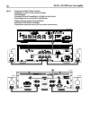
Input Signal Connections
5
The RB-1552 and RB-1582 have conventional RCA type input
connectors, the type found on nearly all audio equipment.
Note:
To prevent loud potentially damaging noises, make sure the
amplifier is turned off when you make any changes to the input
signal configuration.
Select high quality audio interconnect cables. Connect each of the
outputs from the preamplifier or signal processor to the corresponding
input of the amplifier.
Speaker Connection
Speaker Selection
We recommend using loudspeakers with a nominal impedance
of 4 ohms or higher with the RB-1552 and RB-1582. You should
exercise some caution in driving multiple pairs of speakers in parallel
configuration, because the effective impedance the amplifier sees is
cut in half. For example, when driving two pair of 8 ohm speakers,
the amplifier sees a 4 ohm load. When driving multiple speakers in
parallel, it is recommended that you select speakers with a nominal
impedance of 8 ohms or higher. Speaker impedance ratings are
less than precise. In practice, very few loudspeakers will present any
problems for the RB-1552 or RB-1582. See your authorized Rotel
dealer if you have any questions.
Speaker Wire Selection
Use insulated two-conductor stranded wire to connect the amplifier to
the speakers. The size and quality of the wire can have an audible
effect on the performance of the system. Standard speaker wire will
work, but can result in lower output or diminished bass response,
particularly over longer distances. In general, heavier wire will
improve the sound. For best performance, you may want to consider
special high-quality speaker cables. Your authorized Rotel dealer can
help in the selection of appropriate cables for your system.
Polarity and Phasing
The polarity — the positive/negative orientation of the connections
— for every speaker and amplifier connection must be consistent so
all the speakers will be in phase. If the polarity of one connection is
mistakenly reversed, bass output will be very weak and stereo imaging
degraded. All wire is marked so you can identify the two conductors.
There may be ribs or a stripe on the insulation of one conductor. The
wire may have clear insulation with different color conductors (copper
and silver). There may be polarity indications printed on the insulation.
Identify the positive and negative conductors and be consistent with
every speaker and amplifier connection.
Speaker Connection
6
The RB-1552 and RB-1582 have four pairs of color coded binding
posts, two for each channel. These connectors accept bare wire,
connector lugs, or dual banana type connectors (except in the
European Community countries where their use is not permitted).
Route the wire from the amplifier to the speakers. Give yourself enough
slack so you can move the components enough to allow access to the
speaker connectors.
If you are using dual banana plugs, connect them to the wires and
then plug into the backs of the binding posts. The binding posts should
be screwed in all the way (clockwise).
If you are using terminal lugs, connect them to the wires. If you
are attaching bare wires directly to the binding posts, separate the
wire conductors and strip back the insulation from the end of each
conductor. Be careful not to cut into the wire strands. Unscrew (turn
counterclockwise) the binding post. Place the connector lug or wire
around the binding post shaft. Turn the binding post clockwise to
clamp the connector lug or wire firmly in place.
Note:
Be sure there are no loose wire strands that could touch
adjacent wires or connectors.