


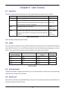
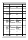
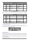
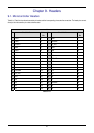
Option Link Settings
Reference Function Fitted Alternative (Removed) Related To
R21 Analog Voltage
Source
Analog Voltage Source is set to
on-board Vcc.
Analog Voltage Source is taken
from external connector.
R46
R46 Analog Voltage
Source
Analog Voltage Source is taken from
external connector.
Analog voltage source is set to
on-board Vcc.
R21
R137 Analog Voltage
Ground
Analog Voltage Ground is routed to
external connector.
Analog Voltage Ground is
disconnected from external
connector.
-
Table 6-11: Analog power supply links.
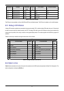
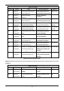
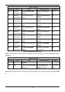
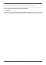
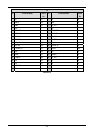
Table 6-12 below describes the function of the option links associated with MCU modes. The default configuration is indicated by BOLD
text.
Option Link Settings
Reference Function Fitted Alternative (Removed) Related To
R44 MCU Mode,
USB unit
The CPU is self powered.
The CPU is power from USB
bus.
J10
R131 MCU Mode Enables SDRAM interface.
Disables SDRAM interface.
J14
R130 MCU Mode,
USB unit
USB dedicated clock is EXTAL × 3
(choose this option if 16 MHz crystal
is used).
USB dedicated clock is
EXTAL
× 4 (choose this option if 12
MHz crystal is used).
J13
R133 MCU Boot mode Serial Boot Mode is selected.
USB Boot Mode is selected.
J16
Table 6-12: MCU mode links.
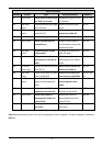
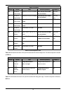
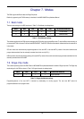
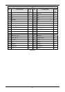
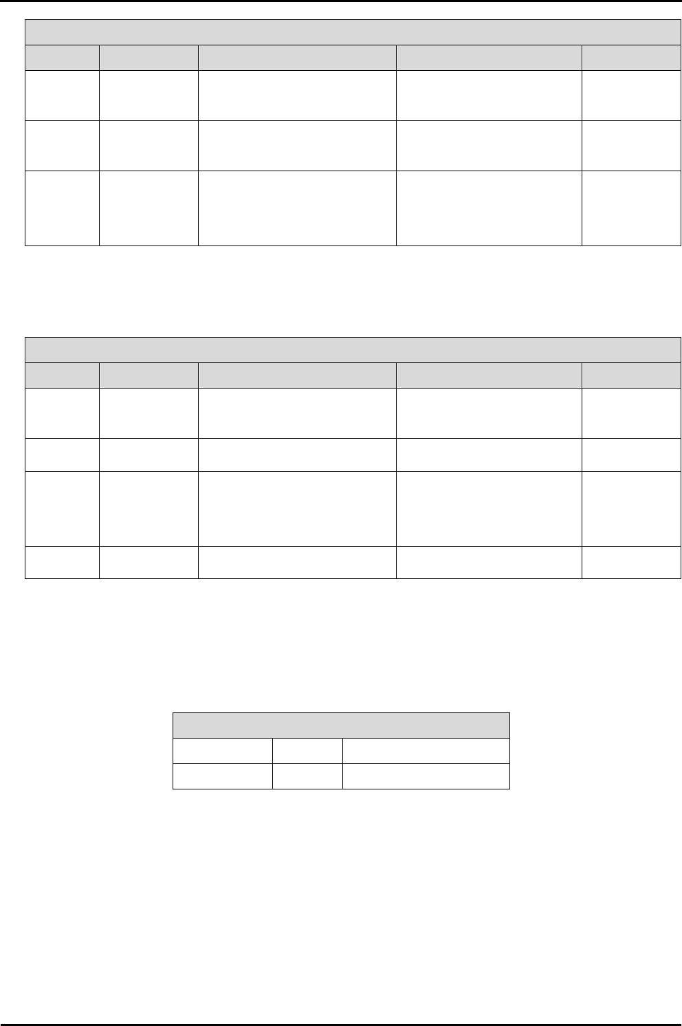
6.7. Oscillator Sources
Two crystal oscillators are fitted on the RSK and used to supply the main clock input to the Renesas microcontroller. Table 6-13 details the
oscillators that are fitted and alternative footprints provided on this RSK:
Component
Crystal (X1) Fitted 12.0 MHz (HC49/4H package)
Crystal (X2) Fitted 32.768 KHz
Table 6-13: Oscillators / Resonators
6.8. Reset Circuit
The CPU Board includes a simple latch circuit that links the mode selection and reset circuit. This provides an easy method for swapping
the device between Boot Mode and User mode. This circuit is not required on customer’s boards as it is intended for providing easy
evaluation of the operating modes of the device on the RSK. Please refer to the hardware manual for more information on the
requirements of the reset circuit.
The Reset circuit operates by latching the state of the boot switch on pressing the reset button. This control is subsequently used to
modify the mode pin states as required.
17