


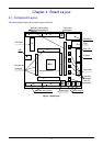

Chapter 6. User Circuitry
6.1. Switches
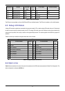
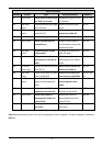
There are four switches located on the CPU board. The function of each switch and its connection are shown in Table 6-1.
Switch Function Microcontroller
RES When pressed, the RSK microcontroller is reset. RESn, Pin 91
SW1/BOOT* Connects to an IRQ input for user controls.
The switch is also used in conjunction with the RES switch to place the device in
BOOT mode when not using the E10A debugger.
IRQ0n, Pin 84
(Port 1 pin 0)
SW2* Connects to an IRQ line for user controls. IRQ1n, Pin 85
(Port 1, pin 1)
SW3* Connects to the ADC trigger input. Option link allows connection to IRQ line.
The option is a pair of 0R links. For more details on option links, please refer
to Sec 6.6.
IRQ3n_ADTRGn,
Pin 87
(Port 1, pin 3)
Table 6-1: Switch Functions
*Refer to schematic for detailed connectivity information.
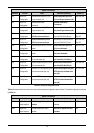
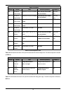
6.2. LEDs
There are six LEDs on the RSK board. The green ‘POWER’ LED lights when the board is powered. The orange BOOT LED indicates the
device is in BOOT mode when lit. The four user LEDs are connected to an IO port and will light when their corresponding port pin is set low.
Table 6-2, below, shows the LED pin references and their corresponding microcontroller port pin connections.
LED Reference (As
shown on silkscreen)
Colour Microcontroller Port Pin
function
Microcontroller
Pin Number
LED0 Green Port B.3 3
LED1 Orange Port C.2 116
LED2 Red Port C.3 117
LED3 Red Port 1.2 86
Table 6-2: LED Port
6.3. Potentiometer
A single turn potentiometer is connected to channel AN0 (P5.0, pin 118) of the microcontroller. This may be used to vary the input analog
voltage value to this pin between AVCC and Ground.
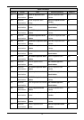
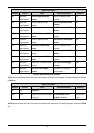
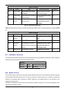
6.4. Serial port
Serial port SCI0 is connected to the standard RS232 header. Serial port SCI5 can optionally be connected to the RS232 header. The
connections to be fitted are listed in the Table 6-3.
10