


Contact Closure Inputs and Outputs
Inputs 1 discrete input
Configuration Single-ended input
Resistance for closure detect < 1kΩ max
Resistance for open detect > 5kΩ min
Input voltage limit 7.000 VDC maximum
(“-” input terminal connected to chassis)
Output 1 discrete output
Configuration Electromechanical relay, dry contacts,
floating, C, NC, NO
Maximum steady-state current 0.5A
Maximum switched current 0.25A
Ground isolation 70V maximum
Connector “Phoenix-style” (a.k.a. “Euro-style”)
detachable terminal block connectors
Network Interface
Physical Network Ethernet
Raw data rate 10 megabits per second
Frame format D.I.X. (Ethernet)
Connector RJ-45 female
Ethernet type 10BASE-T: (via RJ-45)
Cable type 10BASE-T: CAT-3 (or better) twisted pair
Max cable length 10BASE-T: 100 m to hub
Grounding Floating
Transport Network TCP/IP
Internetwork protocol IP
Transport protocol UDP
Application Protocol QSC24
Version 1
Revision 7
General
Physical
Height 1.72" (1RU)
Width 19" (standard rack mount)
Depth 14.84" (37.7 cm), including rear supports
Weight 11 lbs. (5 kg)
Mounting Rear support recommended for portable
or mobile use
Operating Temp. 0 to 50° C
AC Power
Voltage 100-240 VAC (Universal Supply)
Current 1A RMS @ 120V, 1.1A RMS @ 100V,
0.5A RMS @ 230V
Frequency 47–440 Hz
Specifications subject to change.
Architect’s and Engineer’s Specification
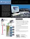
The CM16a Amplifier Network Monitor shall provide input, output,
status monitoring, and control for DataPort equipped QSC power
amplifiers in an Ethernet-TCP/IP based network audio system. Sixteen
independent channels shall be provided, grouped in pairs to support up
to sixteen power amplifier channels.
Amplifier Input Control and Monitoring. For each of the sixteen power
amplifier input signals, the CM16a shall provide level, mute and polarity
control, pre- and post-fader signal level metering and audio monitoring,
and selectable +4 dBu/-10 dBV (3V/1V) input sensitivity.
The CM16a shall provide a page input, separate from the normal
program inputs, whose signal may preempt the program signal of any
or all of the sixteen program channels. This input shall have selectable
+4 dBu/-10 dBV (3V/1V) sensitivity.
The CM16a shall provide for the storage and recall of up to sixteen
different presets, numbered 0 through 15. Each preset shall be a
“snapshot” of all of the CM16a functions and settings. Preset #0 shall be
the default boot-up preset.
Amplifier Output Monitoring. For each of the sixteen power amplifier
outputs, the CM16a shall provide clip detect monitoring, short/open
circuit detect, voltage and current metering, amplifier headroom, load
impedance, real output power to load, and audio monitoring of the
voltage signal.
Amplifier Management. For each of the DataPort connected power
amplifiers, the CM16a shall provide AC standby/operate mode control,
AC power state indication, temperature metering, amp gain settings
(front panel knob position with respect to full output), over-temperature
detection, stereo/parallel/bridge-mono indication, amplifier model
detection, and protect status detection (subject to the capabilities of
each amplifier).
Audio Monitoring Chain. For each of the sixteen program channels, the
CM16a shall provide three monitor points as follows: (1) pre-fader level
control, (2) post-fader level control, or (3) power amplifier output. A
channel’s monitor output may be selected from one of these three
signals, or it may be switched off. The signal at the CM16a’s monitor
output connector shall be the sum of the signal at its monitor input
connector and as many as four of the sixteen channel monitor signals
at one time per CM16a. A monitor level control shall be provided for
each monitor tap point to adjust the individual levels of the channel
monitor signals prior to their being mixed with the monitor input signal.
Contact Closure I/O. The CM16a shall provide one trigger contact-closure
sense input which shall also be TTL signal compatible, and one dry-
contact floating SPDT relay output. These shall be under software control,
with functions definable by the QSControl custom software application.
The contact closure sense input shall be capable of toggling between
presets 14 and 15, regardless of the computer’s connection status.
Data Network. All CM16a functions shall be controlled and monitored
via an Ethernet digital control network using the TCP/IP transport
protocol and the QSC-24 control and monitoring application protocol.
Rear-panel connections shall be provided for 10BASE-T Ethernet
utilizing a standard RJ-45 Unshielded Twisted Pair Category-5
connection. Other than the AC power and bypass switches, the CM16a
shall have no manual controls. A 9-pin, “D” subminiature connector
shall be provided to allow interfacing to an RS-232 connection. This
connector shall be used for CM16a setup, testing, diagnostics, and
limited control functions.
Amplifier Interface. The CM16a’s interface to each power amplifier
DataPort shall be via a HD-15 connector. The amplifier interface shall
use a standard personal computer Video Graphics Adapter (VGA) CRT
monitor cable
1
. This interface shall transmit two amplifier input audio
signals as well as all control and monitoring signals. Special signal
conditioning and grounding techniques shall be used in this interface to
ensure negligible levels of noise and crosstalk.
General. All audio inputs and outputs shall be balanced with a nominal
input level of +4 dBu and maximum level of +21 dBu. Input connectors
shall be of the “Euro-style” depluggable barrier strip type.
1
QSC DataPort cable required for connection with QSC DSP devices.
2
For lengths greater than 2 meters, a QSC DataPort cable is recommended.