


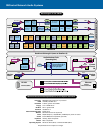
Input Signal
Frequency Response 20 Hz to 20 kHz, ±0.5 dB
10 Hz to 80 kHz, ±3 dB
Distortion <0.01% THD+N @ +4 dBu out
(page input <0.03%)
Dynamic Range >110 dB unweighted (20 Hz–20 kHz)
(page input >100 dB)
Polarity In-phase or reversed
Level Control Range -95.5 to 0 dB in 0.5 dB steps
Precision Attenuator Transients
(“zipper noise”) better than 112 dB below maximum output
Mute >90 dB attenuation
Inputs
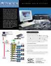
Program inputs 16
Paging input 1 Dedicated input with configurable
routing to any or all 16 input sections
Monitor bus input 1
Connector type “Phoenix-style” (a.k.a. “Euro-style”)
detachable terminal blocks
Type Electronically balanced
Grounding All shield terminals connected
to chassis
Nominal level 1V/3V rms selectable (-10 dBV/+4 dBu)
Maximum level +21 dBu
Impedance 25 kΩ balanced
Common-mode rejection Typical, >50 dB, 20 Hz-20 kHz
Worst Case, >40 dB at 20 kHz
Crosstalk (inter-channel
within DataPort pair) >75 dB separation (20 Hz–20 kHz)
Crosstalk (intra-channel
between DataPorts) >90 dB separation, 20 Hz-20 kHz
measured with all inputs and
outputs terminated
Outputs
Program outputs 16 (via HD-15)
Connector type 8 HD-15 DataPort connections
Cable type VGA monitor cable
1
Qualified length 2 meters
Monitor output 1
Connector “Phoenix-style” (a.k.a. “Euro-style”)
detachable terminal blocks
Type Electronically balanced
Grounding Shield terminal connected to chassis
Nominal level +4 dBu
Maximum level +21 dBu
Output impedance 75Ω balanced
Output load 600Ω min
Power Amplifier Output Monitoring
Output Short Detect* Senses load <1Ω for Stereo/Parallel modes;
<2Ω Bridge Mono mode (default threshold)
Threshold is adjustable in software
Output Open Detect* Senses load >60Ω (default threshold)
Threshold is adjustable in software
Output Voltage Meter Range automatically matches to
amplifier model used
Output Current Meter Range automatically matches to
amplifier model used
Amplifier Headroom Reports remaining available power
Amplifier Gain* Calculates and reports amplifier gain
(knob setting)
*Signal level must be higher than -32 dB, referenced to maximum output of amplifier
Power Amplifier Management
Power Amplifier Interface
Compatibility QSC DataPort-equipped amplifiers
Connector and cable HD-15 VGA cable
1
, 2 meters length
2
qualified (for longer runs, contact QSC’s
Technical Services Department)
Amplifiers Up to 16 channels (8 DataPorts) of
QSC DataPort-equipped amplifiers
Amplifier AC Power Control
AC mode control Switches amplifier between operate
and standby mode
AC power indicator Indicates operate, standby, or
power-down mode
Amplifier Status Monitor
Clip indicator Senses channel clip status
Protect indicator Senses amplifier protect status
Temperature meter Reports amplifier operating temperature
Over-temp. alert Software adjustable threshold (80°C default)
Control Room Foldback Monitoring
Number of Signal
Monitoring Buses per CM16a 1
Number of Channels per CM16a 4 (Maximum number assigned
to monitor mix at one time)
Internal Signal Monitor Points
(each with individual level controls)
Pre-fader input signal 16
Post-fader input signal 16
Power amplifier output 16
Monitor Input Summed with internal monitor mix
at unity gain
Monitor in to monitor out 0 dB, ±1 dB
Nominal level +4 dBu
Maximum level +21 dBu
Input impedance 10kΩ balanced
Configuration Active balanced, shield connected to chassis
Common-mode rejection Worst case, >54 dB at 20 Hz rolling off to
>40 dB at 20 kHz
Typical case, >50 dB 20 Hz-20 kHz
Output Sum of external monitor input and signals
from internal monitor mix
Frequency response 20 Hz–20 kHz, ± 0.5 dB
Distortion <.05% THD @ +4 dBu out
Dynamic range >90.5 dB unweighted, 22 Hz–22 kHz
Noise floor -90.5 dB
Nominal level +4 dBu
Maximum level +21 dBu
Output impedance 75Ω balanced
Output load 600Ω min
Configuration Active balanced
RS-232 Port
Cable Type Null-Modem (a.k.a. Laplink), female 9-pin
D-sub chassis connector
Port Settings Bits per Second 9600
Data Bits 8
Parity none
Stop Bits 1
Flow Control Xon/Xoff
Page Input
Specifications