9
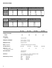
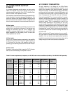
MX 1000a MX 1500a MX 2000a MX 3000a
CONNECTORS (each channel) Input: Barrier strip and 1/4” RTS phone jack
Output: “Touch-Proof” binding posts
COOLING MX 1000a, MX 1500a, MX 2000a: 2-speed fan with back-to-front air flow
MX 3000a: Continuously variable speed fan, with back-to-front air flow
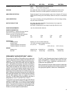
AMPLIFIER PROTECTION Output Averaging
™
short-circuit protection, open circuit, ultrasonic, RF, thermal
muting (thermal limiting also on MX 3000a). Stable into reactive or mismatched
loads.
LOAD PROTECTION Turn-on/turn-off muting, clip limiting (MX 3000a only), DC-fault load grounding
relay with internal fault fuses.
OUTPUT CIRCUIT TYPE MX 1000a, MX 1500a, MX 2000a: Complementary linear stage with
2-step high-efficiency circuit
MX 3000a: Complementary linear stage 3-step high-efficiency circuit
POWER REQUIREMENTS 100, 120, 220-240 VAC, 50/60 Hz
POWER CONSUMPTION
Normal operation: 1/8 power @ 4
Ω
per channel
Maximum: full power @ 2
Ω
per channel
Divide current by 2 for 220-240 VAC operation
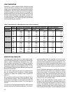
Normal Operation @ 120 VAC 4A 5.5A 7.5A <12A
Maximum @ 120 VAC 22A 29A 38A 58A
DIMENSIONS
Faceplate Width Standard 19" (48.3 cm) Rack Mounting
Chassis Depth 17.9” (45.5 cm) deep (to support rear ears)
Faceplate Height (2 rack spaces) 3.5” (8.9 cm) 3.5” (8.9 cm)
Faceplate Height (3 rack spaces) 5.25” (13.3 cm) 5.25” (13.3 cm)
WEIGHT
Shipping, Lbs 49 lbs/22.2 kg 49 lbs/22.2 kg 62 lbs/28 kg 74 lbs/33.8 kg
Net, Lbs 42 lbs/19 kg 42 lbs/19 kg 54 lbs/24.5 kg 69 lbs/31 kg
OPEN INPUT ARCHITECTURE
™
LEVEL I
On the rear of an MXa or EX amplifier are an upper and
a lower input panel; both are easily removable for future
upgrades. This is the concept of Open Input Architecture,
and the opening in which the panels mount is called the
“slot”. As installed at the factory, the lower is the MXa or
EX standard input panel and the upper one is a blank. A
ribbon cable connects the “slot” panels to the rest of the
amplifier. It carries input signals, speaker output monitor
signals, muting status, and clip activity; these are for
supporting future accessories and remote control sys-
tems. Although the physical dimensions of the MXa and
EX panels are the same, their internal cabling is different
and the MXa platform does not support all the EX
functions. The MXa Open Input Architecture slot thus is
designated as “Level I” and the EX as “Level II.”
The standard input panel shipped with each MXa Series
amplifier has balanced 1/4” (6.3 mm) RTS phone jacks
and barrier strip inputs and the Parallel-Stereo-Bridge
switch. The panel’s circuit board has solder footprints for
passive roll-off circuit components, input isolation trans-
formers, and other special customizations.
The MX-1 Input Expander panel may be installed in the
upper panel position. It features XLR inputs and addi-
tional 1/4” RTS inputs. Installation instructions are in-
cluded with the expansion kit.
Other accessories include a stereo precision attenuator
(for the lower panel position) and a cinema crossover (for
the upper panel position). More are in development.


