11
VI. LONG-TERM OUTPUT
POWER
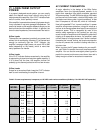
In a properly designed sound system, you can usually
obtain the desired sound level without using the full
output power of the amplifier; if the “CLIP” indicators flash
once in a while, that is perfectly normal.
If the amplifier is operated at extremely high power levels,
it may overheat or may even damage the speakers. The
amount of stress on the amplifier depends largely on the
load and how hard the amplifier drives it. In general, the
lower the load impedance, the more stressful the load is.
8-Ohm Loads
The amplifier can operate at practically any power level
without risk of overheating. However, if it is pushed hard
enough to continually light the “CLIP” indicator, the
amplifier’s average output power can reach 250 to 800
watts (depending on the model), which is more than
many speakers can handle.
4-Ohm Loads
If the “CLIP” indicator flashes occasionally, the amplifier
is approaching its maximum long-term power capacity. If
it is lit about half the time, the amplifier channel will
probably go into thermal protection within a few minutes.
2-Ohm Loads
Except for an occasional flash, keep the “CLIP” indicator
dark to avoid overheating the amplifier channel.
AC CURRENT CONSUMPTION
A major objective in the design of the MXa Series
amplifiers—even the highest-powered models—is to
permit their operation from readily available, standard
AC power sources. The MX 3000a can deliver 1600 watts
per channel into 2-ohm loads—a total of 3200 watts—yet
its rated current draw under “normal conditions” is less
than 12 amperes at 120 volts AC, which is 1440 watts.
How is this possible? First, “normal conditions” in power
amplifier rating means operation, using pink noise as a
source, at an average power level equal to one-eighth of
maximum power. This is recognized by most of the
world’s safety agencies as the loudest you can play
music through an amplifier and still keep the incidence of
clipping to a reasonable minimum. An amplifier’s peak
current draw at full output power into 2 ohms is several
times what the “normal” draw is, but its various protection
circuits will prevent this condition’s lasting more than a
minute or two.
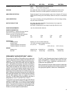
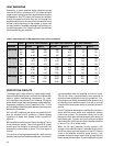
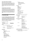
When you plan the AC power hookups for your amplifi-
ers, use Table 2 to predict the current requirements per
amplifier. You can use the one-eighth power figures to
predict the normal continuous current draw, then add a
safety margin to allow for occasional crescendos.
Table 2: Current requirements, in amperes, at 120 VAC under various conditions (divide by 2 for 220–240 VAC operation):
MX 1000a
MX 1500a
MX 2000a
MX 3000a
8+8
4+4
2+2
275 x 2
400 x 2
500 x 2
10
15
22
5.5
7.5
10
3
4
5
1
1
1
8+8
4+4
2+2
400 x 2
600 x 2
750 x 2
14
21
29
7
11
13
4
5.5
6.5
1
1
1
8+8
4+4
2+2
475 x 2
725 x 2
1000 x 2
16
25
38
9.5
15
21
5
7.5
11
1
1
1
8+8
4+4
2+2
850 x 2
1300 x 2
1600 x 2
25
40
58
16
31
42
9.5
15
20
1
1
1
AC Current
@ Full power
Output
powerLoad
MODEL
AC Current
@ 1/3 power
AC Current
@ 1/8 power
AC Current
@ Idle


