


5
III. INPUTS
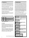
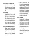
An MXa amplifier features balanced inputs, connected
via barrier strip terminals or 1/4” (6.3 mm) tip/ring/sleeve
phone jacks. The tip of the input jack is wired for “nega-
tive’ or inverted polarity, while the ring is the non-inverting
input. Thus, if the voltage at the tip is positive with respect
to that at the ring, the amplifier channel will produce a
negative voltage at its output.
For use with unbalanced signals, connect the unused
terminal to ground to avoid a reduction in gain caused by
a floating input; use a two-conductor (tip/sleeve) plug, or
connect a jumper between the inverting input terminals
on the barrier strip and their adjacent ground terminal.
MX 1000a INPUTS
The amplifier’s input sensitivity is 1.1 volt rms; at this
signal level and input attenuators set for full gain, the
amplifier will produce full rated power—250 watts, 20Hz-
20kHz, 0.1% THD—into an 8-ohm load. The input imped-
ance is 20 kilohm balanced and 10 kilohm unbalanced,
typical of QSC amplifiers.
MX 1500a INPUTS
The amplifier’s input sensitivity is 1.07 volt rms; at this
signal level and any attenuators set for full gain, the
amplifier will produce full rated power—350 watts, 20Hz-
20kHz, 0.1% THD—into an 8-ohm load. The input imped-
ance is 20 kilohm balanced and 10 kilohm unbalanced,
typical of QSC amplifiers.
MX 2000a INPUTS
The amplifier’s input sensitivity is 1.05 volt rms; at this
signal level and any attenuators set for full gain, the
amplifier will produce full rated power—450 watts, 20Hz-
20kHz, 0.1% THD—into an 8-ohm load. The input imped-
ance is 20 kilohm balanced and 10 kilohm unbalanced,
typical of QSC amplifiers.
MX 3000a INPUTS
The amplifier’s input sensitivity is 1 volt rms; at this signal
level and any attenuators set for full gain, the amplifier will
produce full rated power—800 watts, 20Hz-20kHz, 0.1%
THD—into an 8-ohm load. The input impedance is 20
kilohm balanced and 10 kilohm unbalanced, typical of
QSC amplifiers.
An MXa Series amplifier features a Level I Open Input
Architecture slot. See Section 2 for more information
about Open Input Architecture.
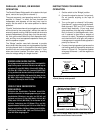
BRIDGED MONO
CHANNEL 2
CH 2
AVIS
RISQUE DE CHOC ELECTRIQUE
NE PAS OUVRIR
RISK OF ELECTRIC SHOCK
DO NOT OPEN
CAUTION
WARNING:
TO REDUCE THE RISK OF FIRE
OR ELECTRIC SHOCK, DO NOT EXPOSE THIS
EQUIPMENT TO RAIN OR MOSTURE.
GND
–
++
–
AUDIO
––
CH 1INPUT
CH 2
TIP NEG RING POS
SLEEVE GND
CH 1
TIP NEG RING POS
SLEEVE GND
STEREO
PARALLEL BRIDGE
–
+
–
+
CHANNEL 1
STEREO 4 OHM MIN/CH.
BRIDGED MONO 8 OHM MIN.
CLASS 2 WIRING
CLASS 1 WIRING MUST BE USED
BRIDGED MONO OPERATION: PLACE BRIDGING SWITCH ON INPUT PANEL
TO BRIDGED POSITION. CONNECT INPUT SIGNAL TO CH 1 ONLY.
CONNECT SPKR (+) TO CH 1 (+) OUTPUT. CONNECT SPEAKER (–) TO
CH 2 (+) OUTPUT. SET CH 2 GAIN FULLY CLOCKWISE AND REGULATE
LEVEL WITH CH 1 GAIN CONTROL.
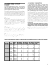
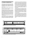
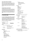
Figure 3: QSC MX 1500a Back Panel (identical to the MX 1000a)
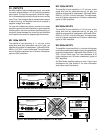
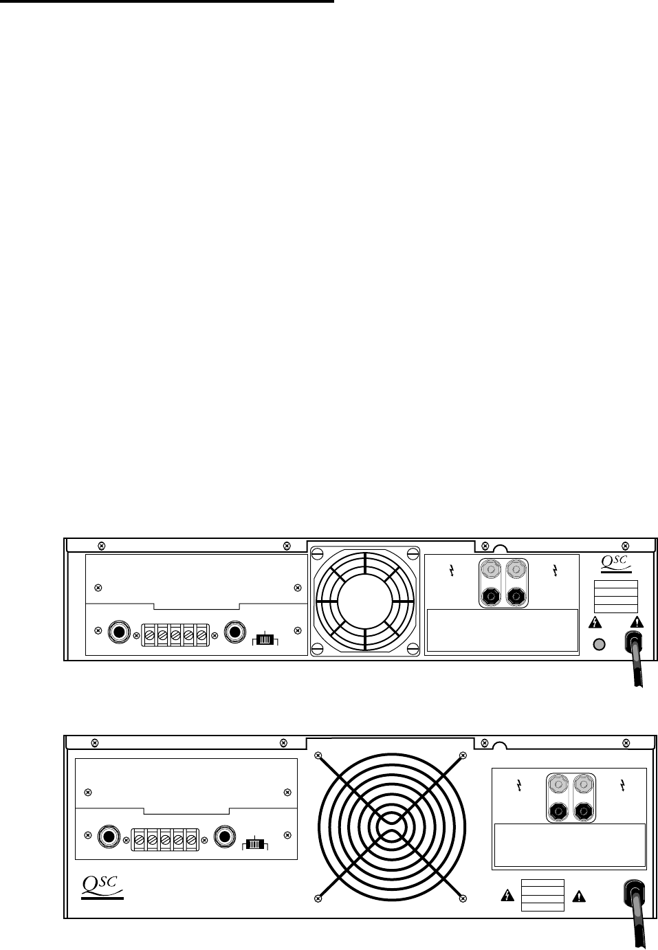
Figure 4: QSC MX 2000a Back Panel (identical to the MX 3000a)