


37
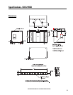
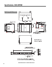
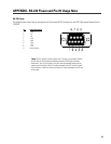
Specifications- ISIS 215PCM Processors
Note: Specifications are subject to change without notice.
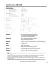
Digital Signal Processor Specifications
Type Freely configurable, custom DSP with software for PC. Computer connection needed only for set up.
Signal Processing Two QSC DSP-3 Processors, 24 bit, 48 kHz., one for each amplifier
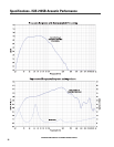
Frequency response at 3 dB below full scale input voltage 20 Hz– 10 kHz ±0.3 dB (XLR inputs on 215PCM rear panel)
20 Hz– 20 kHz ±0.7 dB (XLR inputs on 215PCM rear panel)
20 Hz– 20 kHz±0.2 dB (if using DataPort input on Processors)
Distortion <0.01% THD+N @ +4 dBu out
Delay (throughput) 1.00 millisecond
Dynamic range >93 dB unweighted, 20 Hz– 20 kHz, 1.5V, 4V and 9V sensitivity
>88dB unweighted, 20 Hz– 20 kHz, 18V sensitivity
Polarity In-phase or inverted
Mute >90 dB attenuation
Input Connector type True-Cannon XLR connectors mounted on 215PCM rear panel
Type Electronically balanced
Grounding All shield terminals connected to chassis
Input sensitivity, full scale 1.5, 4.0, 9.0 or 18.0 Vrms, (Units are selectable in software interface)
6, 14.5, 21.5 or 27.5 dBu
3.5, 12.0, 19.0, 25.0 dBv
Input Impedance Discrete Mode- 8.3 k ohm balanced, 3.7 k ohm unbalanced
Combination Mode- 4.15 k ohm balanced, 1.85 k ohm unbalanced
Common-mode rejection >50 dB, 20 Hz– 20 kHz
Crosstalk >75 dB separation, 20 Hz– 20 kHz
Outputs Program outputs hard wired to amplifiers
Post-DSP auxillary outputs Three- 2 (Top Box), 1 (Subwoofer, CH2 output not used)
Type Electronically balanced detachable terminal blocks
Grounding Shield terminal connected to chassis
Post-DSP auxillary output level, full scale 6.0 or 4.0 Vrms; 18.0 or 14.5 dBu; 15.5 or 12.0 dBv (Units are selectable in software interface)
Output impedance 600 ohms balanced
QSC System Manager Connectivity (applicable only to users employing QSC System Manager)
System Interface Compatibility QSC DataPort amplifier network monitors
Cable QSC DPC-X DataPort cable, male-male (various lengths are available , contact QSC’s Technical
Services Department)
DataPorts Used 2 (1 per Processor)
Amplifier status monitor features
Clip indicator Senses channel clipping
Protect indicator Senses amplifier protect status
AC Power Status Reports standby/operate mode
RS-232 Ports (used for configuring each Processor’s DSP chain)
Number of ports Two (one for each processor)
Cable Type Normal 9-pin serial cable, male-to-female
Maximum Length 25 feet (7.6 meters)
Communication Settings Automatic (unless other software using port)
DSP Capabilities (freely configurable DSP “blocks”, use as many of any block until DSP “resources” are consumed)
High-Pass Filter Low-Pass Filter High-Shelf Filter Low-Shelf Filter Limiter Compressor Delay
Polarity Parametric EQ Level Meter 2 to 1 Mixer 1 to 2 Splitter Mute Fader
Pink & White Noise Source Variable Frequency Tone Source Clip & Protect Indication available if operating the DSP real-time from PC
External Contact Closure Sensing (pin #9 of RS-232, operates with ”Switched Gain” objects in Signal Manager software)